
11.7 Modbus TCP Programming and Experimentation
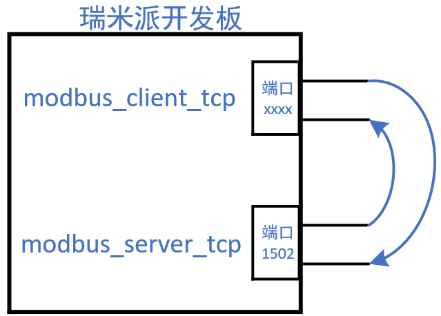
This course does not support sensors that use the Modbus TCP protocol, so we will write two programs:
① modbus_server_tcp.c: Simulate a Modbus TCP sensor
② modbus_client_tcp.c: Operate the sensor
The program structure is shown in the figure below:
No special connections are required on the hardware.
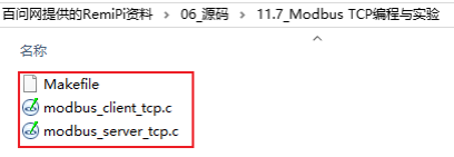
The source code for this section is located in the following directory:
Next, we will explain the code using a scenario analysis method. Suppose the following commands are executed on the development board:
Swipe left and right to view the complete content
# ./modbus_server_tcp 127.0.0.1 &# ./modbus_client_tcp 127.0.0.1 led1 on
11.7.1 Server Initialization and Waiting for Connection
In “modbus_server_tcp.c”, the code is as follows:
Swipe left and right to view the complete content
41 ctx = modbus_new_tcp(argv[1], 1502);42 if (ctx == NULL) {43 fprintf(stderr, "Unable to allocate libmodbus context\n");44 return -1;45 }4647 //modbus_set_slave(ctx, SERVER_ID);4849 mb_mapping = modbus_mapping_new_start_address(0,50 NB_BITS, /* 5 DO registers, corresponding to beep1, beep2, led1, led2, led3 */51 0,52 NB_INPUT_BITS,53 0,54 NB_REGISTERS,55 0,56 NB_INPUT_REGISTERS); /* 2 AI registers, corresponding to temperature and humidity */57 memset(mb_mapping->tab_bits, 0, NB_BITS);58 memset(mb_mapping->tab_input_registers, 0, NB_INPUT_REGISTERS*2);5960 memset(old_bits, 0, NB_BITS);61 memset(old_regs, 0, NB_INPUT_REGISTERS*2);6263 s = modbus_tcp_listen(ctx, 1);64 modbus_tcp_accept(ctx, &s);-
Line 41: Allocates a modbus_t structure containing the IP and port.
-
Line 47: Sets the sensor address, this line is commented out, in the Modbus TCP protocol, even if the client sends requests with different device addresses, the server will receive all these requests (it ignores the device address).
-
Lines 49~56: Allocates Modbus registers. It simulates a sensor based on the “11.5.2 Sensor Point Table”.
-
Lines 57~58: Initializes the DO and AI registers to 0.
-
Lines 60~61: Sets the values of two arrays to 0; these two arrays will be used to compare with the Modbus registers to determine if the Client program has modified these values.
-
Lines 63~64: This is different from the Modbus RTU protocol; they initialize the socket and wait for a client connection.

11.7.2 Client Initialization and Connection Request
In “modbus_client_tcp.c”, the code is as follows:
Swipe left and right to view the complete content
33 ctx = modbus_new_tcp(argv[1], 1502);34 if (ctx == NULL) {35 fprintf(stderr, "Unable to allocate libmodbus context\n");36 return -1;37 }3839 modbus_set_slave(ctx, SERVER_ID);4041 if (modbus_connect(ctx) == -1) {42 fprintf(stderr, "Connection failed: %s\n", modbus_strerror(errno));43 modbus_free(ctx);44 return -1;45 }-
Line 33: Allocates a modbus_t structure, setting the IP and port.
-
Line 39: Sets the Modbus sensor address to access.
-
Line 41: Sends a connection request.

11.7.3 Server Waiting for Request
In “modbus_server_tcp.c”, the code is as follows:
Swipe left and right to view the complete content
66 while (1)67 {68 do {69 rc = modbus_receive(ctx, query);70 /* Filtered queries return 0 */71 } while (rc == 0);72-
Line 69: Waits for a client to send a request.

11.7.4 Client Sends Request
In “modbus_client_tcp.c”, the code is as follows:
Swipe left and right to view the complete content
65 if (!strcmp(argv[2], "beep1"))66 addr = 0;67 if (!strcmp(argv[2], "beep2"))68 addr = 1;69 if (!strcmp(argv[2], "led1"))70 addr = 2;71 if (!strcmp(argv[2], "led2"))72 addr = 3;73 if (!strcmp(argv[2], "led3"))74 addr = 4;7576 if (addr == -1)77 {78 usage(argv[0]);79 return -1;80 }8182 if (!strcmp(argv[3], "on"))83 status = 1;84 else85 status = 0;8687 rc = modbus_write_bit(ctx, addr, status);88 if (rc == 1)89 {90 printf("modbus_write_bit ok\r\n");91 }92 else93 {94 printf("modbus_write_bit err: %d, %s\r\n", rc, strerror(errno));95 }-
Lines 65~85: Set addr and status based on parameters.
-
Line 87: Sends a request to “write AO register”.

11.7.5 Server Processes Request and Responds
In “modbus_server_tcp.c”, the code is as follows:
Swipe left and right to view the complete content
75 if (rc >= 0) {7677 printf("Get query for UID %d\r\n", query[6]);7879 /* Simulate temperature and humidity using random numbers */80 mb_mapping->tab_input_registers[0] = rand() % 1000; /* Temperature, unit: 0.1C */81 mb_mapping->tab_input_registers[1] = rand() % 1000; /* Humidity, unit: 0.1% */8283 rc = modbus_reply(ctx, query, rc, mb_mapping);84 }85 if (rc == -1) {86 printf("Connection closed!\r\n");87 modbus_close(ctx);88 modbus_tcp_accept(ctx, &s);89 }9091 /* Based on the values set by the client, pretend to operate the buzzer and LED */92 if (mb_mapping->tab_bits[0] != old_bits[0])93 {94 printf("set beep1 %s\r\n", mb_mapping->tab_bits[0] ? "on" : "off");95 old_bits[0] = mb_mapping->tab_bits[0];96 }9798 if (mb_mapping->tab_bits[1] != old_bits[1])99 {100 printf("set beep2 %s\r\n", mb_mapping->tab_bits[1] ? "on" : "off");101 old_bits[1] = mb_mapping->tab_bits[1];102 }103104 if (mb_mapping->tab_bits[2] != old_bits[2])105 {106 printf("set led1 %s\r\n", mb_mapping->tab_bits[2] ? "on" : "off");107 old_bits[2] = mb_mapping->tab_bits[2];108 }109110 if (mb_mapping->tab_bits[3] != old_bits[4])111 {112 printf("set led2 %s\r\n", mb_mapping->tab_bits[4] ? "on" : "off");113 old_bits[3] = mb_mapping->tab_bits[4];114 }115116 if (mb_mapping->tab_bits[4] != old_bits[4])117 {118 printf("set led3 %s\r\n", mb_mapping->tab_bits[4] ? "on" : "off");119 old_bits[4] = mb_mapping->tab_bits[4];120 }-
Line 77: Prints the “device address” from the request packet sent by the client; you can use this “device address” to operate different devices, but this program does not use it.
-
Lines 80~81: Fills the AO registers with random numbers to simulate temperature and humidity. If the client reads the temperature and humidity, the “modbus_reply” on line 83 will respond with these values.
-
Line 83: Uses “modbus_reply” to send a response packet to the client.
-
Lines 85~89: If there is an error, wait for the client to establish a connection again.
-
Lines 91~120: Operates the hardware based on the data sent by the client (here, it only prints information).

11.7.6 Hands-on Experiment
Upload the code to Ubuntu.
Then, execute the following command in Ubuntu to compile:
Swipe left and right to view the complete content
$ source /opt/remi-sdk/environment-setup-aarch64-poky-linux$ make$ scp modbus_client_tcp [email protected]:/home/root$ scp modbus_server_tcp [email protected]:/home/rootFinally, execute the following commands on the development board (first execute modbus_server):
Swipe left and right to view the complete content
# cd /home/root# ./modbus_server_tcp 127.0.0.1 &# ./modbus_client_tcp 127.0.0.1 led1 onGet query for UID 4set led1 onmodbus_write_bit okConnection closed!# ./modbus_client_tcp 127.0.0.1 readGet query for UID 4Temperature = 38.6C, Humidity = 49.2%Get query for UID 4Temperature = 64.9C, Humidity = 42.1%Get query for UID 4Temperature = 36.2C, Humidity = 2.7%

Need product and solution support?
Please scan the code to register

Need technical support?
If you have any questions while using Renesas MCU/MPU products, you can scan the QR code below or copy the URL into your browser to open the Renesas Technical Forum to find answers or get online technical support.

https://community-ja.renesas.com/zh/forums-groups/mcu-mpu/
To be continued
Recommended Reading

libmodbus Scenario Analysis – RZ MPU Industrial Control Tutorial Series (39)

Master Device Read Response and Common Interface Functions – RZ MPU Industrial Control Tutorial Series (40)

Modbus Interface and Data Processing – RZ MPU Industrial Control Tutorial Series (41)
For more exciting content, please follow us


Need product and solution support?
Please scan the code to register