
-Begin-
Basic Knowledge of Modbus
The Modbus communication protocol was published by Modicon (now Schneider Electric) in 1979 for communication with programmable logic controllers (PLCs). Today, Modbus has become the industry standard for communication protocols in the industrial field and is commonly used for connecting industrial electronic devices. Modbus, being the most widely used protocol in the industrial sector, has the following characteristics compared to other communication protocols:
-
The Modbus protocol is open, publicly available, and has no copyright requirements.
-
The Modbus protocol supports various electrical interfaces, including RS232, RS485, TCP/IP, and can transmit over various media such as twisted pair, fiber optics, infrared, and wireless.
-
The Modbus protocol message frame format is simple, compact, and easy to understand.
It is easy for users to understand and use, and manufacturers can easily develop and integrate it, facilitating the formation of industrial control networks. The Modbus protocol is an application layer message transmission protocol, including three message types: ASCII, RTU, and TCP. The protocol itself does not define the physical layer but defines the message structure that controllers can recognize and use.
When using serial transmission, the Modbus protocol can choose either RTU or ASCII mode, specifying the message, data structure, commands, and response methods, and requiring data validation.
ASCII mode uses LRC validation, while RTU mode uses 16-bit CRC validation. When transmitted over Ethernet, TCP is used, and this mode does not use validation because the TCP protocol is a reliable, connection-oriented protocol.
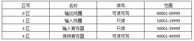
The Modbus protocol defines four storage areas, illustrated in the following table with a commonly used length of five segments:
The Modbus protocol also defines over twenty function codes, but only eight are commonly used for reading and writing to the storage areas mentioned above, as shown in the following table:

To achieve better results in learning Modbus, it is essential to use related debugging software.
The three essential tools for learning Modbus are Modbus Poll, Modbus Slave, and VSPD. The Modbus Poll software is mainly used to simulate a Modbus master station or Modbus client, while the Modbus Slave software is primarily used to simulate a Modbus slave or Modbus server. VSPD, short for Configure Virtual Serial Port Driver, is used to create virtual serial ports on a computer.
Analysis of Modbus RTU/ASCII Protocol
Modbus RTU and Modbus ASCII have almost the same message data sending format, but there are some differences, specifically:
1. Modbus ASCII has a start character (:) and an end character (CR LF), which serve as markers for the beginning and end of a frame of data, while Modbus RTU does not have such markers and requires time intervals to determine the start and end of a message frame. The protocol specifies a time of 3.5 character periods, meaning that before the start of a message frame, there must be a free time greater than 3.5 character periods, and after the end of a message frame, there must also be a free time of 3.5 character periods; otherwise, a sticky packet situation may occur.
Note: The 3.5 character period is a specific time, but this time is related to the baud rate. In serial communication, one character consists of 1 start bit, 8 data bits (in general cases), 1 parity bit (or none), and 1 stop bit (in general cases), so one character includes 11 bits. Therefore, 3.5 characters equal 38.5 bits. The baud rate indicates the number of binary bits transmitted per second; for example, at a baud rate of 9600, 3.5 character periods = 1000/9600*38.5=4.01ms.
2. The two have different validation methods: Modbus RTU uses CRC cyclic redundancy check, while Modbus ASCII uses LRC longitudinal redundancy check.
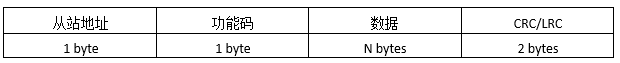
The following analysis focuses on specific messages. The message format of the Modbus protocol on a serial link is shown below:
Reading Output Coils
The sending message format is as follows:

Meaning of the sending message:
Read the output coil of slave 1, starting address 0x13=19, corresponding address 00020, number of coils 0x1B=27, meaning read the output coil of slave 1, addresses from 00020 to 00046, a total of 27 coil status values.
Note: The starting address in the protocol refers to the index, while the subsequent addresses refer to specific addresses. For any storage area, the index starts from 0, but the corresponding specific address is related to the storage area. For example, for output coils, 0 corresponds to 00001; for input coils, 0 corresponds to 10001; for input registers, 0 corresponds to 30001; for holding registers, 0 corresponds to 40001.
The return message format is as follows:

Meaning of the return message:
The return message for slave 1’s output coils from 00020 to 00046, a total of 27 coil status values, with a return byte count of 4, represented as CD 6B B2 05.
CD=1100 1101 corresponds to 00020-00027
6B=0110 1011 corresponds to 00028-00035
B2=1011 0010 corresponds to 00036-00043
05=0000 0101 corresponds to 00044-00046
Reading Input Coils
The sending message format is as follows:
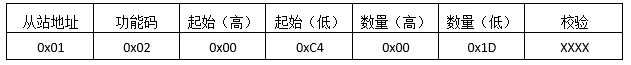
Meaning of the sending message:
Read the input coil of slave 1, starting address 0xC4=196, corresponding address 10197, number of coils 0x1D=29, meaning read the input coil of slave 1, addresses from 10197 to 10225, a total of 29 coil status values. The return message format is as follows:

Meaning of the return message:
The return message for slave 1’s input coils from 10197 to 10225, a total of 29 coil status values, with a return byte count of 4, represented as CD 6B B2 05.
CD=1100 1101 corresponds to 10197-10204
6B=0110 1011 corresponds to 10205-10212
B2=1011 0010 corresponds to 10213-10220
05=0000 0101 corresponds to 10221-10225
Reading Holding Registers
The sending message format is as follows:
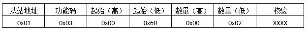
Meaning of the sending message:
Read the holding register of slave 1, starting address 0x6B=107, corresponding address 40108, number of registers 0x02=2, meaning read the holding register of slave 1, addresses from 40108 to 40109, a total of 2 register values. The return message format is as follows:

Meaning of the return message:
The return message for slave 1’s holding registers from 40108 to 40109, a total of 2 register values, with a return byte count of 4, represented as 02 2B 01 06.
40108 corresponds to the value 0x022B,
40109 corresponds to the value 0x0106.
Reading Input Registers
The sending message format is as follows:

Meaning of the sending message:
Read the input register of slave 1, starting address 0x6B=107, corresponding address 30108, number of registers 0x02=2, meaning read the input register of slave 1, addresses from 30108 to 30109, a total of 2 register values. The return message format is as follows:

Meaning of the return message:
The return message for slave 1’s input registers from 30108 to 30109, a total of 2 register values, with a return byte count of 4, represented as 02 2B 01 06.
30108 corresponds to the value 0x022B,
30109 corresponds to the value 0x0106.
Preset Single Coil
The sending message format is as follows:
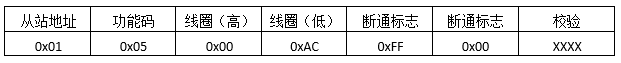
Meaning of the sending message:
Preset the value of a single coil for slave 1, coil address 0x00AC=172, corresponding address 00173, the on/off flag 0xFF00 indicates set, while 0x0000 indicates reset, meaning set the output coil 00173 of slave 1. The return message format is as follows:

Meaning of the return message:
The preset single output coil returns the original message.
Preset Single Register
The sending message format is as follows:

Meaning of the sending message:
Preset the value of a single holding register for slave 1, register address 0x0087=135, corresponding address 40136, write value 0x039E, meaning preset the value of holding register 40136 for slave 1 to 0x039E.
The return message format is as follows:

Meaning of the return message:
The preset single holding register returns the original message.
Preset Multiple Coils
The sending message format is as follows: please ignore this image

Meaning of the sending message:
Preset the values of multiple coils for slave 1, coil address 0x0013=19, corresponding address 00020, number of coils 0x0A=10, write value 0xCD00, meaning preset slave 1 coils from 00020 to 00027=0xCD=1100 1101, and from 00028 to 00029=0x00=0000 0000.
The return message format is as follows:

Meaning of the return message:
The return message for preset multiple output coils is the original message with the byte count and specific bytes removed.
Preset Multiple Registers
The sending message format is as follows:

Meaning of the sending message:
Preset the values of multiple registers for slave 1, register address 0x0087=135, starting address 40136, number of registers 0x02=2, ending address 40137, write values 0x0105 and 0x0A10, meaning preset register 40136 for slave 1 to 0x0105 and register 40137 to 0x0A10.
The return message format is as follows:

Meaning of the return message:
The return message for preset multiple holding registers is the original message with the byte count and specific bytes removed.
-END-
For backend replies, reply with ‘software’ or ‘article’ to get more software and related original technical articles.
Feel free to follow my public account and reply ‘join group’ to join the technical exchange group according to the rules.
Click ‘read more’ to quickly enter the free live class; likes, views, shares, and favorites are welcome.