
The AT89C2051 is a streamlined version of the 51 microcontroller, omitting the P0 and P2 ports, and featuring only 20 pins. However, it integrates a very useful analog comparator, making it particularly suitable for developing simplified 51 application systems. After all, when developing simple products, we often do not need all 32 I/O ports, making the AT89C2051 a more appropriate choice due to its smaller chip size. Additionally, the AT89C2051 operates at a minimum voltage of 2.7V, allowing it to be used in portable products powered by two AA batteries.
This article explains the AT89S51 and AT89C2051 microcontrollers from the 51 series family produced by ATMEL. These two microcontrollers are currently among the most commonly used, with the AT89S51 being the standard 51 microcontroller. Of course, its functionality is more powerful than earlier 51 microcontrollers, supporting in-system programming (ISP) technology and featuring a built-in hardware watchdog…
1. Introduction to AT89S51 Microcontroller Pins
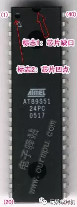
The AT89S51 is available in three packaging options: PDIP, PLCC, and TQFP, with the most common being the 40-pin dual in-line PDIP package, as shown in the figure below.
The chip has a total of 40 pins, arranged in a counterclockwise order starting from the pin next to the notch on the chip (see right image), numbered sequentially from 1 to 40. The top of pin 1 has a dimple (see lower image). Among the 40 pins of the microcontroller, there are 2 power pins, 2 external crystal oscillator pins, 4 control pins, and 32 programmable I/O pins divided into 4 groups of 8.
 |
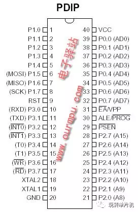 |
1. Main Power Pins (2 pins)
VCC (Pin 40): Power input, connects to +5V power supply
GND (Pin 20): Ground connection
2. External Crystal Oscillator Pins (2 pins)
XTAL1 (Pin 19): Input of the internal oscillation circuit
XTAL2 (Pin 20): Output of the internal oscillation circuit
3. Control Pins (4 pins)
RST/VPP (Pin 9): Reset pin; a high level for 2 machine cycles will reset the microcontroller.
ALE/PROG (Pin 30): Address latch enable signal
PSEN (Pin 29): External memory read select signal
EA/VPP (Pin 31): Program memory external/internal selection; connecting to low level reads instructions from external program memory, while connecting to high level reads from internal program memory.
4. Programmable Input/Output Pins (32 pins)
The AT89S51 microcontroller has 4 groups of 8-bit programmable I/O ports, namely P0, P1, P2, and P3, with each port having 8 bits (8 pins), totaling 32 pins. Each pin can be programmed, for example, to control motors, traffic lights, neon lights, etc. When developing products, these programmable pins are utilized to achieve the desired functionality, allowing you to unleash your imagination and realize your goals 🙂 They are incredibly powerful…
P0 Port (Pin 39 to Pin 32): 8-bit bidirectional I/O port lines, named P0.0 to P0.7
P1 Port (Pin 1 to Pin 8): 8-bit quasi-bidirectional I/O port lines, named P1.0 to P1.7
P2 Port (Pin 21 to Pin 28): 8-bit quasi-bidirectional I/O port lines, named P2.0 to P2.7
P3 Port (Pin 10 to Pin 17): 8-bit quasi-bidirectional I/O port lines, named P3.0 to P3.7
The above is a brief introduction to the pins of the AT89S51 microcontroller. Other microcontrollers in the 51 series family, such as the 8031, 8051, and 89C51, have pins that are compatible with the AT89S51, although some pin function definitions may differ.
2. Introduction to AT89C2051 Microcontroller Pins
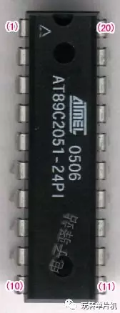
The AT89C2051 is a 20-pin compact package with 2K internal program memory and 15 programmable I/O port lines, lacking the 16 I/O lines of the P0 and P2 ports, and integrating an analog comparator. The pin arrangement of the AT89C2051 microcontroller is shown in the figure below.
 |
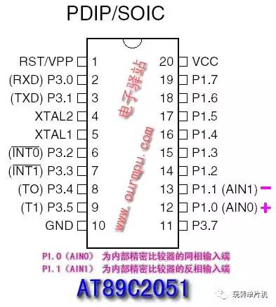 |
Chip physical image / Chip pin functions
The chip has a total of 20 pins, arranged in a counterclockwise order starting from the pin next to the notch (see above image), numbered sequentially from 1 to 20. Among the 20 pins of the microcontroller, there are 2 power pins, 2 external crystal oscillator pins, 1 reset pin, and 15 programmable I/O pins from P1 and P3 ports.
1. Main Power Pins (2 pins)
VCC (Pin 20): Power input, connects to +5V power supply
GND (Pin 10): Ground connection
2. External Crystal Oscillator Pins (2 pins)
XTAL1 (Pin 5): Input of the internal oscillation circuit
XTAL2 (Pin 4): Output of the internal oscillation circuit
3. Control Pins (1 pin)
RST/VPP (Pin 1): Reset pin; a high level for 2 machine cycles will reset the microcontroller.
4. Programmable Input/Output Pins (15 pins)
P1 Port: 8-bit quasi-bidirectional I/O port lines, P1.0 to P1.7, totaling 8 pins
P3 Port: 8-bit quasi-bidirectional I/O port lines, P3.0 to P3.5 and P3.7, totaling 7 pins
You may have noticed that the standard 51 microcontroller has 32 programmable I/O port lines. After the AT89C2051 omits the P0 and P2 ports, which have 16 I/O lines, it should still have 16 I/O lines. However, it only has 15. Where did the other line go?! As mentioned earlier, the AT89C2051 integrates an analog comparator, which occupies one I/O pin for its output, specifically P3.6. This pin is not brought out, resulting in one less I/O line. In programming, P3.6 can only be used to read the state of the comparator and cannot be used like other I/O pins to drive external indicators or devices. However, the analog comparator is very useful, as it eliminates the need for an external comparator during development. The right image shows the principle of the comparator.
3. Introduction to Main Performance Parameters
AT89S51
-
Fully compatible with the MCS-51 product instruction set
-
4k bytes of in-system programmable (ISP) Flash memory
-
1000 erase/write cycles
-
Operating voltage range of 4.0-5.5V
-
Full static operating mode: 0Hz-33MHz
-
Three-level program encryption lock
-
128×8 bytes of internal RAM
-
32 programmable I/O port lines
-
2 16-bit timers/counters
-
6 interrupt sources
-
Full-duplex serial UART channel
-
Low power idle and power-down modes
-
Interrupts can wake the system from idle mode
-
Watchdog timer (WDT) and dual data pointers
-
Power-down identification and fast programming features
-
Flexible in-system programming (ISP byte or page write mode)
AT89C2051
-
Fully compatible with the MCS-51 product instruction set
-
2k bytes of reprogrammable Flash memory
-
1000 erase/write cycles
-
Operating voltage range of 2.7V-6V
-
Full static operation: 0Hz-24MHz
-
Two-level encrypted program memory
-
128×8 bytes of internal RAM
-
15 programmable I/O port lines
-
2 16-bit timers/counters
-
6 interrupt sources
-
Programmable serial UART channel
-
Output ports can directly drive LEDs
-
Built-in analog comparator
-
Low power idle and power-down modes


Some Screenshots of Electronic Books

【Complete Set of Hardware Learning Materials Collection】