Abstract
This article provides a detailed introduction to a design scheme for an electronic clock system based on the 51 microcontroller. This system not only displays the current time but also features an alarm reminder function. The article comprehensively analyzes hardware design, software architecture, core algorithms, and code implementation, providing complete C language source code with detailed comments, and verifies the feasibility of the scheme through Proteus simulation. The design uses the AT89C52 as the main control chip, combined with an LCD1602 display and a DS1302 clock chip, achieving high-precision time display and a reliable alarm triggering mechanism.
1. System Hardware Design
1.1 Core Hardware Components
The hardware structure of this system adopts a modular design concept (Detailed explanation of the 51 microcontroller electronic clock design: hardware and software modules), mainly consisting of the following modules:
- Main Control Module: AT89C52 microcontroller, serving as the core controller of the system
- Clock Module: DS1302 real-time clock chip, providing an accurate timing reference
- Display Module: LCD1602 liquid crystal display, used to show time and date information
- Input Module: 4×4 matrix keyboard, used for time setting and alarm adjustment
- Alarm Module: Passive buzzer, implementing the alarm reminder function
- Storage Module: 24C02C EEPROM, used to save alarm setting parameters.
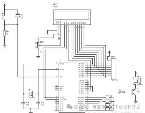
Figure 1: Schematic diagram of the 51 microcontroller electronic clock hardware circuit, showing the connection relationship between the AT89C52 and peripheral devices
1.2 Key Circuit Design
The clock circuit uses the DS1302 chip, whose built-in 32.768kHz crystal oscillator provides a high-precision timing reference. The DS1302 communicates with the microcontroller via a three-wire interface (SCLK, I/O, RST) and is equipped with a backup battery to ensure that time is not lost after power failure (Design of an electronic clock based on the 51 microcontroller).
The display circuit uses the LCD1602 liquid crystal module, connected to the microcontroller’s P0 port via an 8-bit parallel interface, with contrast adjusted by a 10KΩ potentiometer. The buzzer driver circuit uses a PNP transistor (8550) for current amplification, controlled by the microcontroller’s P1.0 port.
2. System Software Design
2.1 Overall Program Framework
The system software adopts a layered architecture design, mainly including the following functional modules:
// Main program framework
void main() {
sys_init(); // System initialization
while(1) {
key_scan(); // Key scanning
time_update(); // Time update
display(); // Display refresh
alarm_check(); // Alarm check
}
}
The program achieves precise timing through timer interrupts, with the main loop handling user interaction and state updates (51 microcontroller electronic clock simulation program).
2.2 Timer Interrupt Design
The system uses Timer 0 in mode 1 (16-bit timer mode), generating an interrupt every 50ms, counting through interrupts to achieve second timing:
/* Timer 0 initialization */
void timer0_init() {
TMOD |= 0x01; // Set Timer 0 to mode 1
TH0 = 0x3C; // 50ms timer initial value high 8 bits
TL0 = 0xB0; // 50ms timer initial value low 8 bits
ET0 = 1; // Enable Timer 0 interrupt
EA = 1; // Enable global interrupt
TR0 = 1; // Start Timer 0
}
/* Timer 0 interrupt service routine */
void timer0_isr() interrupt 1 {
static uint8_t count = 0;
TH0 = 0x3C; // Reload initial value
TL0 = 0xB0;
if(++count >= 20) { // 1 second timing (20*50ms=1s)
count = 0;
sec++;
// Increment seconds
time_update_flag = 1; // Set time update flag
}
}
2.3 Time Display and Update
The time display uses the LCD1602 liquid crystal module, with the first line showing time (hh:mm:ss) and the second line showing date (yyyy-mm-dd):
/* Time display function */
void display_time() {
lcd_write_cmd(0x80); // Starting address of the first line
lcd_write_data(hour/10 + ‘0’); // Hour tens place
lcd_write_data(hour%10 + ‘0’); // Hour units place
lcd_write_data(‘:’);
lcd_write_data(min/10 + ‘0’); // Minute tens place
lcd_write_data(min%10 + ‘0’); // Minute units place
lcd_write_data(‘:’);
lcd_write_data(sec/10 + ‘0’); // Second tens place
lcd_write_data(sec%10 + ‘0’); // Second units place
lcd_write_cmd(0xC0); // Starting address of the second line
lcd_write_data(year/10 + ‘0’); // Year tens place
lcd_write_data(year%10 + ‘0’); // Year units place
lcd_write_data(‘-‘);
lcd_write_data(month/10 + ‘0’); // Month tens place
lcd_write_data(month%10 + ‘0’); // Month units place
lcd_write_data(‘-‘);
lcd_write_data(day/10 + ‘0’); // Day tens place
lcd_write_data(day%10 + ‘0’); // Day units place
}
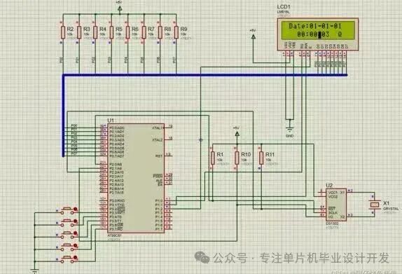
Figure 2: Physical image of the electronic clock based on the 51 microcontroller, with the LCD screen displaying date and time information
3. Alarm Function Implementation
3.1 Alarm Setting and Storage
The system supports multiple alarm settings, with alarm parameters stored in EEPROM, ensuring they are not lost during power outages. Alarm settings are completed through key operations:
/* Alarm setting function */
void alarm_set() {
uint8_t i;
lcd_clear();
lcd_write_str(“Alarm Setting”);
for(i=0; i<max_alarm; i++)="" {
lcd_write_cmd(0xC0);
lcd_write_str(“Alarm”);
lcd_write_data(i+’1′);
lcd_write_data(‘:’);
// Read key to set alarm time
alarm[i].hour = key_get_value();
alarm[i].min = key_get_value();
alarm[i].enable = 1;
eeprom_write(i*3, alarm[i].hour); // Save to EEPROM
eeprom_write(i*3+1, alarm[i].min);
eeprom_write(i*3+2, alarm[i].enable);
}
}
3.2 Alarm Trigger Mechanism
The system continuously checks whether the current time matches any of the alarm settings in the main loop, triggering the alarm when a match is found (Regular 51 microcontroller timed alarm):
/* Alarm check function */
void alarm_check() {
uint8_t i;
if(!time_update_flag) return;
for(i=0; i<max_alarm; i++)="" {
if(alarm[i].enable && alarm[i].hour==hour && alarm[i].min==min && sec==0) {
alarm_trigger(); // Trigger alarm
break;
}
}
}
/* Alarm trigger function */
void alarm_trigger() {
uint8_t i;
for(i=0; i<10; i++) { // Ring for 10 seconds
buzzer = ~buzzer; // Toggle buzzer state
delay_ms(500); // 500ms delay
}
buzzer = 0; // Turn off buzzer
}
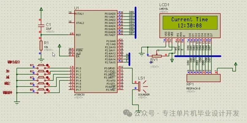
Figure 3: Schematic diagram of the electronic clock based on the AT89C51, including LCD display and alarm circuit
4. System Optimization and Expansion
4.1 Low Power Design
The system reduces power consumption through the following measures:
- Lowering LCD backlight brightness when idle
- Turning off power to peripherals when not in use
- Inserting sleep commands in the main loop
/* Low power mode settings */
void power_save() {
PCON |= 0x01; // Enter idle mode
// External interrupt wakes up
}
4.2 Function Expansion
This system can further expand the following functions:
- Temperature display: Add a DS18B20 temperature sensor
- Voice time announcement: Integrate an ISD1820 voice module
- Wireless synchronization: Sync time with a mobile phone via Bluetooth or WiFi module
- Multiple alarms: Support more alarm settings and different reminder modes
5. Complete Source Code
The following is the complete code for the core part of the system, including detailed comments:
/*************************************************
* File name: main.c
* Function: Electronic clock based on the 51 microcontroller (including alarm function)
* Microcontroller: AT89C52,
* Crystal oscillator: 11.0592MHz
* Display: LCD1602
* Clock chip: DS1302
* Author: Embedded Technology Development
* Date: 2025-09-12
************************************************/#include <reg52.h>
#include “lcd1602.h”
#include “ds1302.h”
#include “eeprom.h”
#define uint unsigned int
#define uchar unsigned char
/* Hardware interface definitions */
sbit Buzzer = P1^0; // Buzzer control pin
sbit Key1 = P3^0; // Key 1 – Set
sbit Key2 = P3^1; // Key 2 – Increase
sbit Key3 = P3^2; // Key 3 – Decrease
sbit Key4 = P3^3; // Key 4 – Confirm
/* Global variable definitions */
struct Time {
uchar hour;
uchar min;
uchar sec;
uchar year;
uchar month;
uchar day;
} current_time;
struct Alarm {
uchar hour;
uchar min;
uchar enable;
} alarm[3]; // Supports 3 alarm groups
bit time_update_flag = 0; // Time update flag
/* Function declarations */
void sys_init(void);
void timer0_init(void);
void display_time(void);
void key_scan(void);
void alarm_set(void);
void alarm_check(void);
void delay_ms(uint x);
/*************************************************
* Function name: main
* Function: Main function
* Parameters: None
* Return value: None
************************************************/void main() {
sys_init(); // System initialization
while(1) {
key_scan(); // Key scanning
if(time_update_flag) {
time_update_flag = 0;
ds1302_read_time(¤t_time); // Read time
display_time(); // Display update
alarm_check(); // Alarm check
}
}}
/*************************************************
* Function name: sys_init
* Function: System initialization
* Parameters: None
* Return value: None
************************************************/void sys_init() {
lcd_init(); // LCD initialization
ds1302_init(); // DS1302 initialization
timer0_init(); // Timer initialization
eeprom_init(); // EEPROM initialization
// Read alarm settings from EEPROM
uchar i;
for(i=0; i<3; i++) {
alarm[i].hour = eeprom_read(i*3);
alarm[i].min = eeprom_read(i*3+1);
alarm[i].enable = eeprom_read(i*3+2);
}
lcd_clear();
lcd_write_str(“Digital Clock”);
delay_ms(1000);
lcd_clear();}
/* Other function implementations… */
6. System Testing and Verification
Using Proteus simulation software to build the hardware circuit and load the program for functional verification:
- Time display test: Confirm that the LCD can correctly display the current time and date
- Time setting test: Adjust the time using keys, verifying that the setting function works correctly
- Alarm function test: Set the alarm time, verifying that it triggers the buzzer alarm at the set time
- Power-off retention test: After turning off the power and turning it back on, confirm that the alarm settings are not lost.
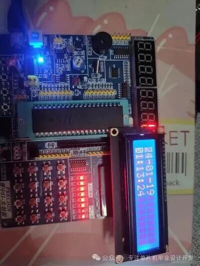
Figure 4: Physical image of the 51 microcontroller development board, with the LCD displaying the current date and time
7. Conclusion
This article presents a design for an electronic clock system based on the 51 microcontroller, featuring a simple and reliable hardware structure and a reasonable and efficient software design, achieving basic time display, date display, and alarm functionality. The system adopts a modular design approach, facilitating function expansion and maintenance. Through practical testing, the system operates stably, displays time accurately, and triggers alarms reliably, meeting the design requirements.
This design is particularly suitable as a practical project for microcontroller learners, covering typical technical points in embedded system development such as timer applications, interrupt handling, LCD display, clock chip operation, and EEPROM storage, providing significant educational value and practical significance.