Hello everyone, welcome to <span>LiXin Embedded</span>.
In the world of embedded development, SPI (Serial Peripheral Interface) is undoubtedly a well-known name. It acts like an efficient “courier,” quickly transferring data between microcontrollers, sensors, ADCs, DACs, and other devices. With its high speed, simplicity, and ease of implementation, SPI has become a favorite in countless embedded systems.
However, for beginners, the four-wire structure, clock signals, and mode configurations of SPI can be a bit confusing. Don’t worry! This article will take you from zero to understanding all aspects of SPI in a straightforward manner. By the end, you will not only grasp the principles of SPI but also feel confident using it in your projects!
What is SPI?
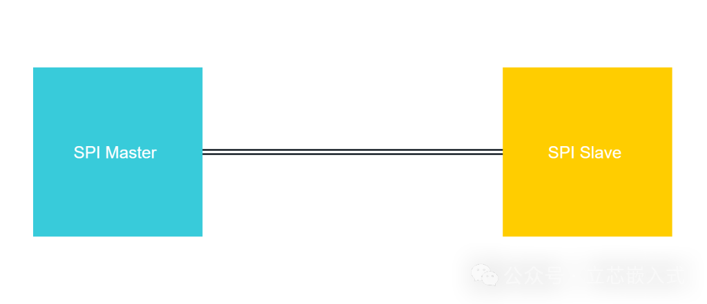
SPI, short for Serial Peripheral Interface, is a synchronous, serial, full-duplex communication protocol designed for short-distance data exchange between devices. It adopts a master-slave architecture, where one master device controls multiple slave devices, achieving efficient communication through four lines.
In simple terms, SPI is like a conversation scenario: the master device is the big brother, responsible for issuing commands and controlling the pace; the slave devices are the little brothers, obediently following instructions and responding. Data is transmitted bit by bit through dedicated lines, making it fast and efficient.
The “Four-Wire Family” of SPI
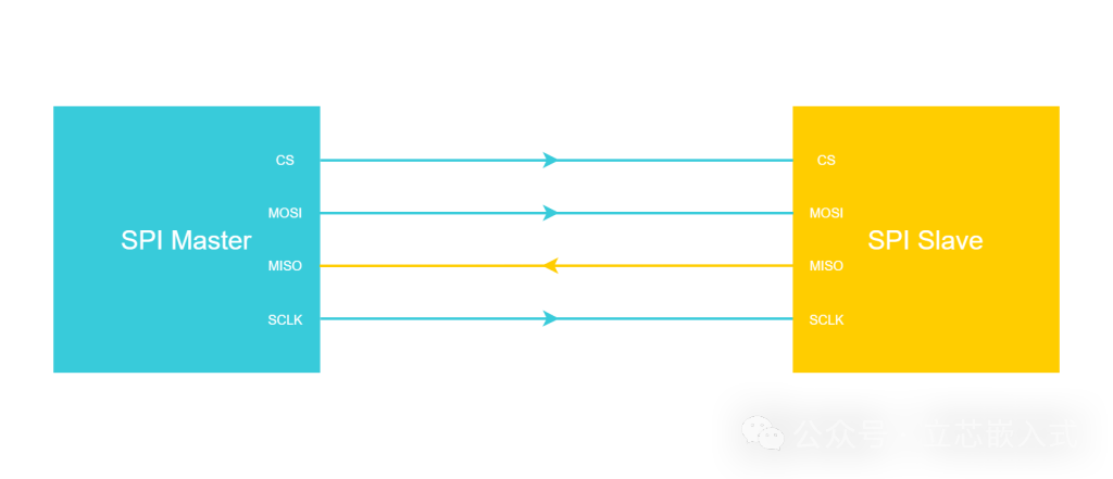
To understand SPI, we first need to recognize its core—four communication lines. Let’s assume we have the simplest scenario: one master device connected to one slave device.
The four lines of SPI are:
- MOSI (Master Output Slave Input): The line for data output from the master device to the slave device.
- MISO (Master Input Slave Output): The line for data input to the master device from the slave device.
- SCLK (Serial Clock): The clock signal line generated by the master device, responsible for synchronizing the rhythm of data transmission.
- CS (Chip Select, or SS, Slave Select): The chip select signal line used by the master device to select which slave device to communicate with.
Communication Process
The typical process of SPI communication is as follows:
- The master device pulls down the CS line of a specific slave device to select it.
- The master device generates a clock signal on the SCLK line, controlling the rhythm of data transmission.
- Data is transmitted bidirectionally through the MOSI and MISO lines simultaneously: the master device sends data to the slave device while the slave device simultaneously returns data to the master device.

The data transmitted each time is typically an 8-bit, 16-bit, or 32-bit “word.” For example, to transmit an 8-bit data, 8 clock cycles are needed, with 1 bit transmitted per cycle, and both MOSI and MISO working simultaneously, ensuring high efficiency!
Because there is a dedicated clock line (SCLK) for synchronization, SPI is referred to as a synchronous protocol; data is transmitted serially bit by bit, so it is a serial protocol; and since MOSI and MISO work simultaneously, it is a full-duplex protocol.
Push-Pull or Open-Drain? The Direction of SPI Lines
The directionality of the four SPI lines is very clear:
| Pin | Master Device | Slave Device |
|---|---|---|
| SCLK | Output | Input |
| CS | Output | Input |
| MOSI | Output | Input |
| MISO | Input | Output |
Due to the fixed direction, SPI pins use a push-pull mode, meaning the pins can actively output high or low levels, providing strong driving capability and stable signals.
This is different from the I2C protocol. I2C lines are bidirectional and use an open-drain mode to prevent both master and slave devices from driving the line simultaneously, which could cause a short circuit. The unidirectional line design of SPI makes communication simpler and more direct, but it also means it does not support multiple master devices like I2C.
Clock Signal: The “Metronome” of SPI
The clock signal (SCLK) of SPI is generated by the master device, acting like the conductor of an orchestra, ensuring that the data transmission rhythm between the master and slave devices is consistent. The master device is usually a microcontroller, while the slave device may be a sensor (like an accelerometer) or a memory chip.
Unlike UART, SPI does not have start/stop bits; each clock cycle directly transmits one bit of data and receives one bit of data. Therefore, the clock frequency (also called baud rate) of SPI directly determines the transmission speed.
Limitations of Clock Speed
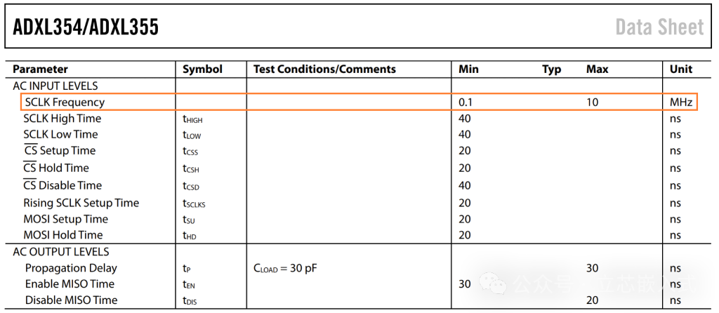
Theoretically, the clock frequency of SPI can be very high, even reaching hundreds of megahertz. However, in practice, the processing capability of the slave device often becomes the bottleneck. For example, the SPI interface of the ADXL355 accelerometer supports a maximum of 10MHz; exceeding this frequency, it cannot keep up.
Additionally, at high frequencies, parasitic parameters (capacitance, inductance) of the lines may cause signal distortion, affecting communication reliability. Therefore, when selecting the clock frequency, it is essential to refer to the slave device’s datasheet to ensure a balance between speed and stability.
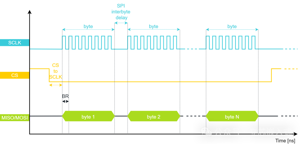
A Little “Overhead”
Although SPI theoretically has no additional overhead, in actual communication, delays from pulling the CS low to the first clock edge, byte gaps, etc., will introduce a small amount of overhead, slightly reducing the effective data rate.
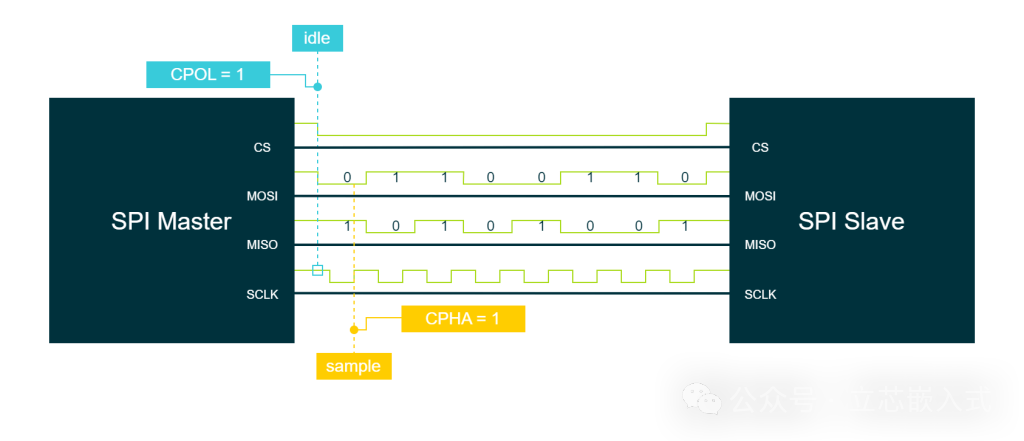
The Four Modes of SPI: The Combination of CPOL and CPHA
SPI has four operating modes determined by Clock Polarity (CPOL) and Clock Phase (CPHA). These two parameters control at which edge of the clock signal data is sampled and sent.
- CPOL (Clock Polarity): Determines the level of the clock when idle.
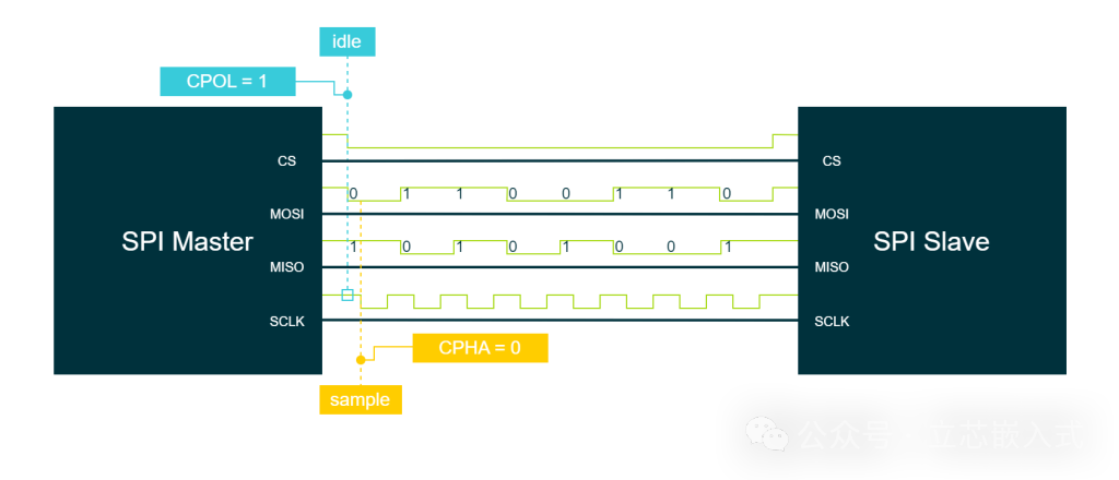
- CPOL = 0: Idle low level.
- CPOL = 1: Idle high level.
- CPHA (Clock Phase): Determines at which edge of the clock data is sampled.
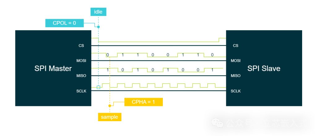
- CPHA = 0: Sampled at the first clock edge.
- CPHA = 1: Sampled at the second clock edge.
The combinations of the four modes are as follows:
| SPI Mode | CPOL | CPHA | Sampling Edge |
|---|---|---|---|
| Mode 0 | 0 | 0 | Rising Edge |
| Mode 1 | 0 | 1 | Falling Edge |
| Mode 2 | 1 | 0 | Falling Edge |
| Mode 3 | 1 | 1 | Rising Edge |
How to Understand These Modes?
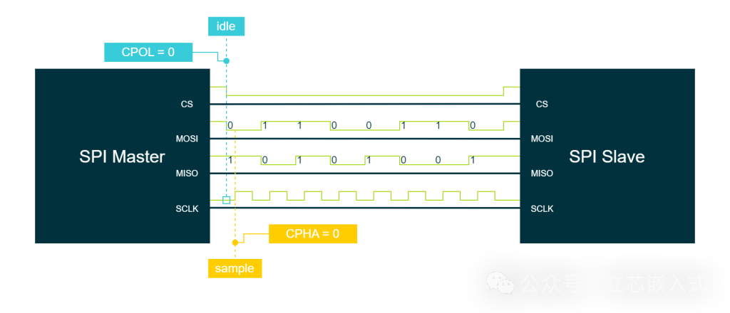
Taking Mode 0 (CPOL=0, CPHA=0) as an example:
- The clock is low when idle (CPOL=0).
- Data is sampled at the first clock edge (rising edge) (CPHA=0).
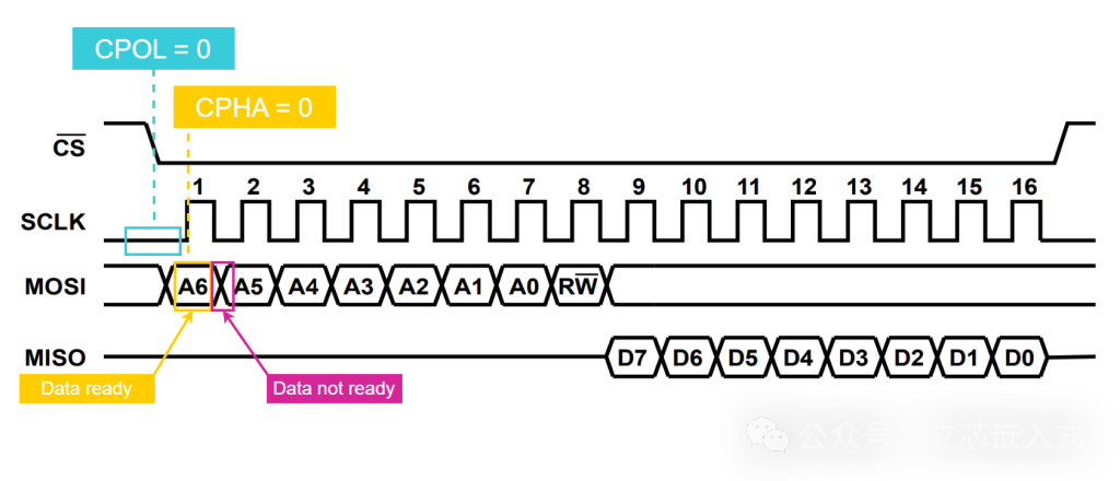
This means that the master and slave devices need to prepare data before the rising edge and sample each other’s data at the rising edge.
The other modes are similar, differing only in the starting level of the clock and the sampling edge. In practical use, the master device must configure the same mode as the slave device; otherwise, communication will fail. The datasheet usually specifies the supported modes of the slave device, for example, the ADXL355 supports Mode 0.
Chip Select (CS): The “Access Card” of SPI
CS (Chip Select) signal is used by the master device to “call out” the slave device. CS is active low, meaning when the master device pulls down the CS line of a specific slave device, that slave device is selected and communication begins.
The CS signal also plays an important role: when CS is high, the MISO, MOSI, and SCLK lines of the slave device enter a high-impedance state, preventing line conflicts. This is especially important in scenarios with multiple slave devices.
Two Topologies of SPI: Independent Mode and Daisy Chain
SPI supports two connection methods: Independent Mode and Daisy Chain Mode.
Independent Mode
In independent mode, each slave device has its own CS line, and the master device communicates with a specific slave device by pulling down that CS line. All slave devices share the SCLK, MOSI, and MISO lines.
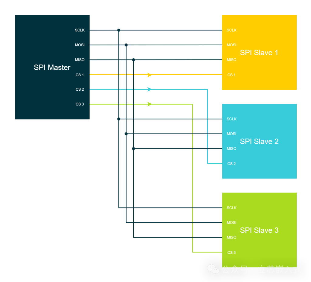
Advantages:
- The master device can flexibly choose which slave device to communicate with, allowing for free time allocation.
- Suitable for scenarios requiring independent control of multiple devices.
Disadvantages:
- The number of CS lines increases with the number of slave devices, occupying more GPIO (3 common lines + N CS lines).
Daisy Chain
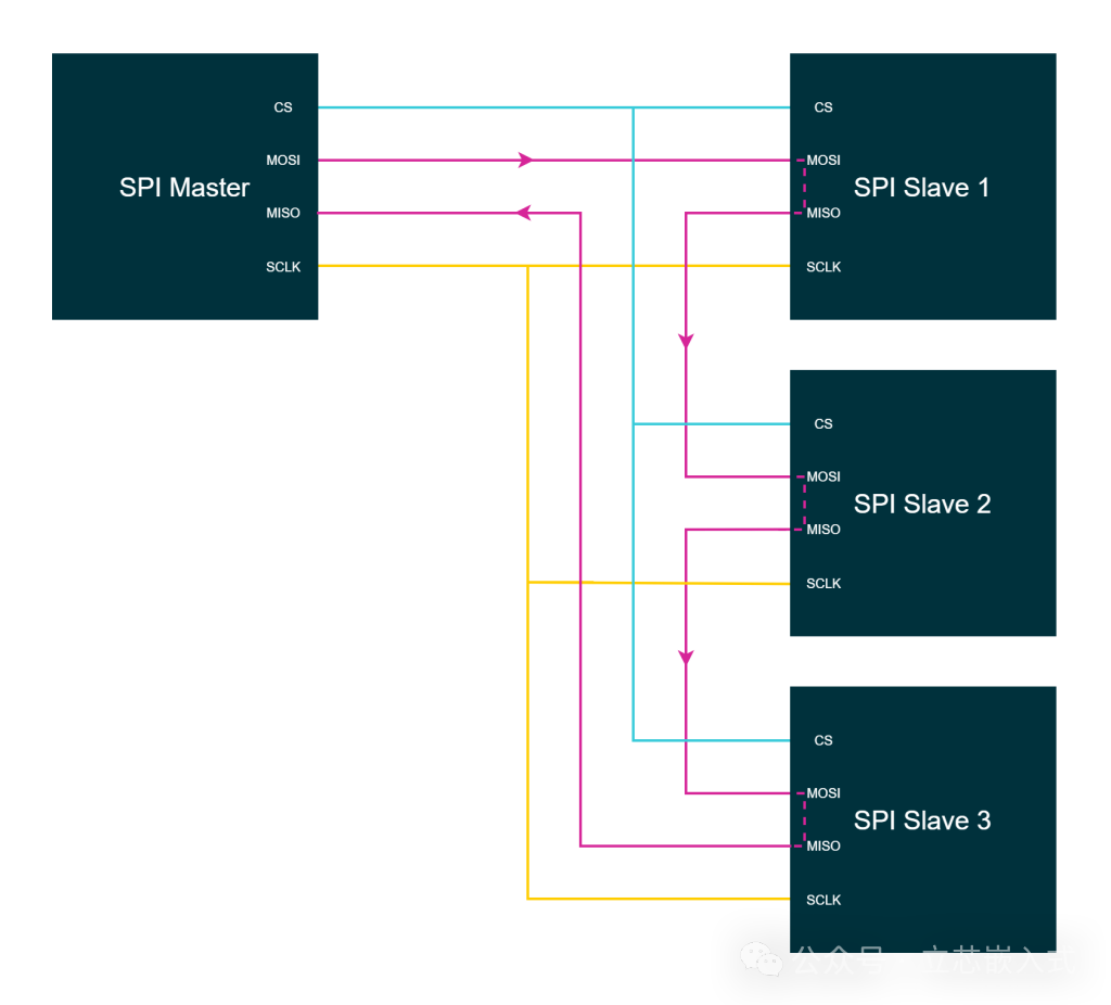
In daisy chain mode, all slave devices share the SCLK and CS lines, while the data lines are connected in series: the master device’s MOSI connects to the first slave device’s MOSI, the first slave device’s MISO connects to the second slave device’s MOSI, and so on, with the last slave device’s MISO returning to the master device’s MISO.
Advantages:
- Only 4 lines are needed, saving GPIO.
- Suitable for scenarios with many slave devices but simple communication needs.
Disadvantages:
- Data must pass through each preceding slave device, resulting in higher latency.
- Communication must occur in order; it is not possible to jump directly to the last device in the chain.
- Not all slave devices support daisy chaining.
For example, suppose there are 3 slave devices, each with a 16-bit data frame. To communicate with the third slave device, 48 bits (3×16 bits) need to be transmitted, as the data must first pass through the first two slave devices.
Conclusion
The SPI protocol, with its simplicity, efficiency, and flexibility, has become a star protocol in embedded communication. Its four-wire structure (MOSI, MISO, SCLK, CS) enables full-duplex communication, clock modes (CPOL and CPHA) ensure data synchronization, and the chip select mechanism flexibly controls communication with multiple devices. Whether in independent mode or daisy chain, SPI can adapt to different scenarios.