A Comprehensive Guide to CAN Bus DBC Files: From Basics to Practice

Happy Teacher’s Day
Introduction: Why are DBC Files Necessary?
In modern automotive electronic systems, the Controller Area Network (CAN) bus is one of the most important communication protocols. It allows for reliable data exchange between Electronic Control Units (ECUs), enabling various functions from engine management to body control. However, the CAN protocol itself only defines the physical layer and data link layer, specifying how to transmit data frames but not the meaning of the data.
This is where the value of DBC files comes in. A DBC (Database CAN) file is a text format file that contains the necessary information to describe all messages and signals on a CAN network. It can be said that a DBC file is the dictionary of the CAN bus, informing engineers of the specific meaning of each bit in every message.
#1
Basic Structure of a DBC File
A complete DBC file consists of multiple sections, each describing different aspects of the CAN network:
1. Version and New Symbols
This is the beginning part of the DBC file, usually containing version information (which may be empty) and new symbol declarations.
2. Baud Rate Definition
Defines the baud rate of the CAN bus, such as 500Kbps or 250Kbps.
3. Node Definition
Lists the names of all ECU nodes in the network.
4. Message Definition
Defines the basic information of CAN messages:
Message Object Identifier
Message ID (decimal)
Message Name
Data Length (bytes)
5. Signal Definition
Defines specific signals within the message:
Signal Identifier
Signal Name
Start Bit | Length Byte Order + Sign (Little Endian/Big Endian)
Scaling Factor and Offset
Signal Value Range
Unit
Node receiving this signal
6. Signal Value Description
Provides a readable description for signal values, mapping numerical values to meaningful strings.

#1
Detailed Writing of DBC Files
1. Determine Network Requirements
Before starting to write a DBC, it is essential to clarify:
What ECU nodes are in the network
What information each node needs to send and receive
The real-time requirements of the communication
The precision and range requirements of the data
2. Define Message Structure
Message ID Allocation
CAN message IDs come in two formats: standard frame (11 bits) and extended frame (29 bits). ID allocation should consider:
Message priority (the smaller the ID value, the higher the priority)
Functional group (powertrain, body control, diagnostics, etc.)
Sending node
Data length determination
The data field length of a CAN message is 0-8 bytes. The length should be determined based on actual data needs to avoid wasting bandwidth.
3. Design Signal Layout
Byte Order and Sign
Byte Order: 0 indicates big-endian (Motorola format), 1 indicates little-endian (Intel format)
Sign: + indicates unsigned, – indicates signed
Signal Layout Strategy
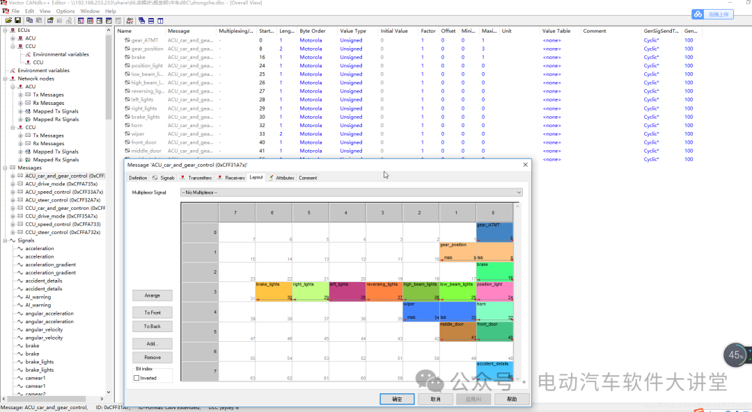
Reasonably arrange signal positions within an 8-byte message:
According to DBC definitions:
4. Set Conversion Rules
Scaling Factor and Offset
Physical Value = (Raw Value × Scaling Factor) + Offset
Value Description Table
Provide readable descriptions for enumerated signals:
5. Define Network Nodes
Clarify the sending and receiving relationships of each ECU:

#1
DBC File Toolchain
1. Editing Tools
CANdb++ Editor: Official tool from Vector
Kvaser Database Editor: Free tool from Kvaser
Online Editors: Web tools like CANdb.io
2. Code Generation
DBC files can be converted into data structures for various programming languages:
C/C++ header files
Python parsing scripts
MATLAB/Simulink data dictionaries
CAPL scripts (for CANoe testing)
3. Testing and Validation
Using tools like CANoe and CANalyzer, you can:
Import DBC files and simulate network communication
Monitor and analyze actual network data
Automate test case execution
Best Practices and Considerations
Consistency in Naming Conventions
Use meaningful names (e.g., EngineSpeed instead of Sig1)
Maintain consistent naming styles (camel case or underscore)
Document Completeness
Add comments for each signal
Maintain a change log
Version Management
Use tools like Git to manage DBC file versions
Ensure compatibility with software versions
Performance Optimization
Reasonably package signals to reduce the number of messages
Consider bandwidth utilization
Scalability Considerations
Leave enough reserved bits for future functionalities
Design backward-compatible message structures

#1
Conclusion
The DBC file, as the cornerstone of CAN bus development, is not only a carrier of data definitions but also a communication bridge for the entire automotive electronic system development. A well-designed DBC file can:
Improve development efficiency
Reduce communication costs
Enhance system reliability
Facilitate testing and validation
As automotive electronic architectures evolve towards centralized systems, the importance of DBC files has not diminished; rather, it continues to play a crucial role in the transition to Service-Oriented Architecture (SOA). Mastering the skills of writing DBC files remains an essential capability for automotive electronic engineers.