In the field of modern architectural lighting, intelligent and refined control has become the mainstream trend. The Ankerui DALI bus intelligent lighting system, as a solution that meets the current lighting technology demands, offers flexible control methods and convenient installation and debugging, making it widely applicable in large public buildings such as hospitals, schools, hotels, airports, and sports venues. Today, we will comprehensively analyze the application points of this system from its core features, hardware selection, wiring installation to debugging and operation.
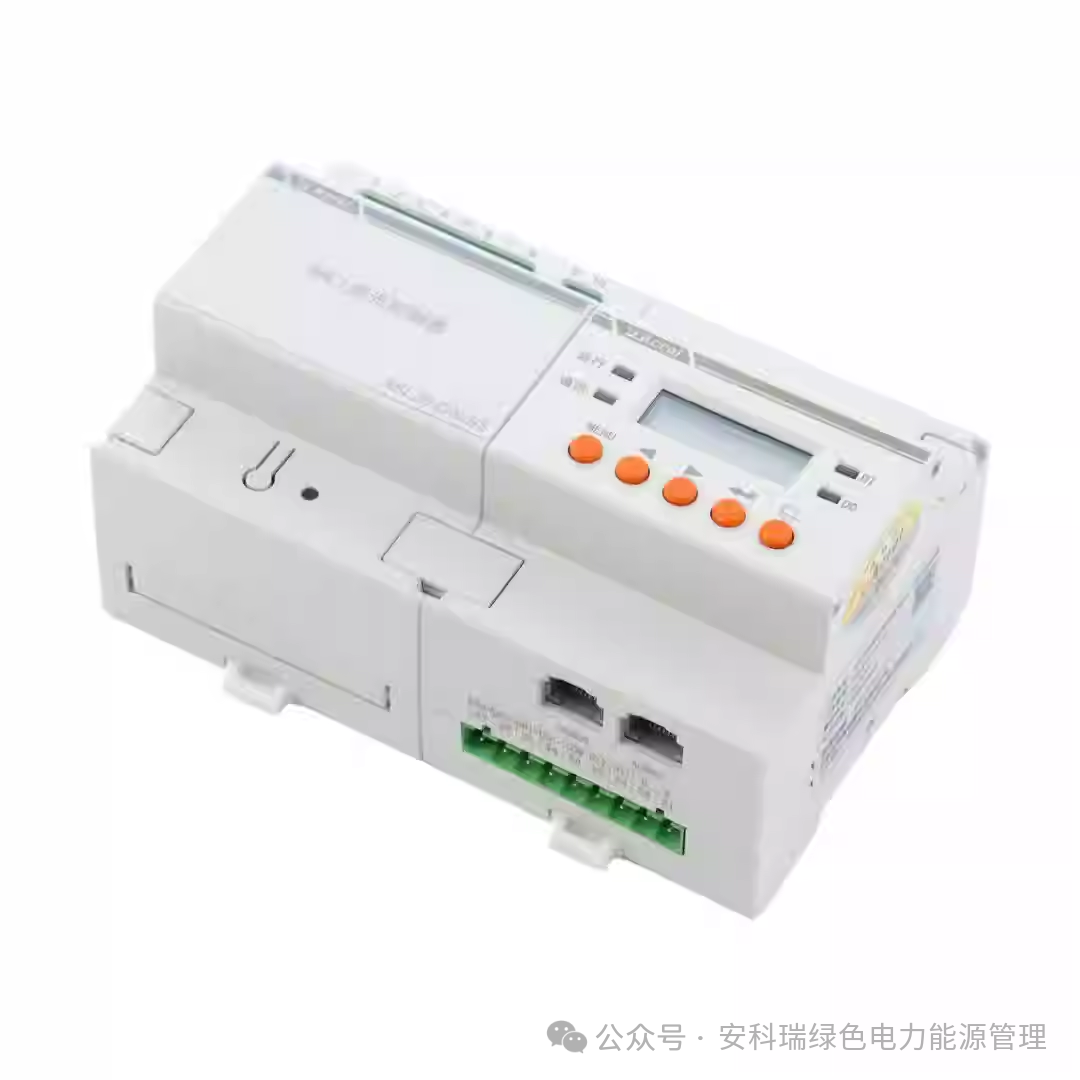
1. What is the DALI Bus Intelligent Lighting System?
DALI, or “Digital Addressable Lighting Interface,” is an internationally recognized standard that primarily aims to break down compatibility barriers between different brands of dimming devices. Whether planners are selecting products or property management is replacing components later, they are not limited to a single supplier, significantly enhancing system flexibility and cost control.
Compared to traditional lighting control, the core advantage of the DALI system lies in its “precise addressing”: each luminaire has an independent address, allowing for independent control of individual lights or any group of lights through system software, even if they are on the same high-voltage circuit. This means that after installation, users can modify the lighting scheme at any time according to scene requirements (such as dimming in conference rooms or energy-saving modes in corridors) without changing the wiring, truly achieving “on-demand lighting.”
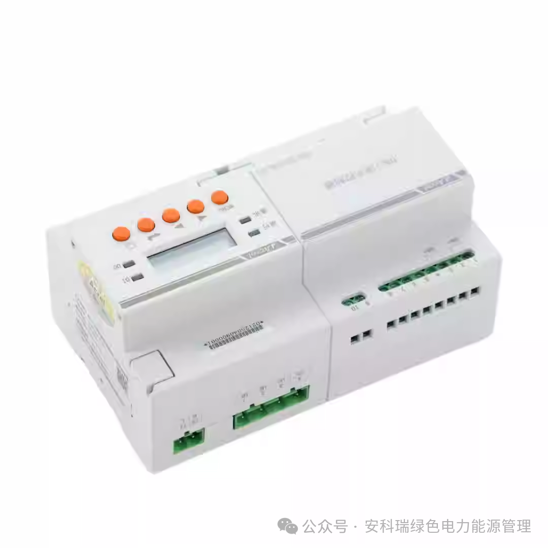
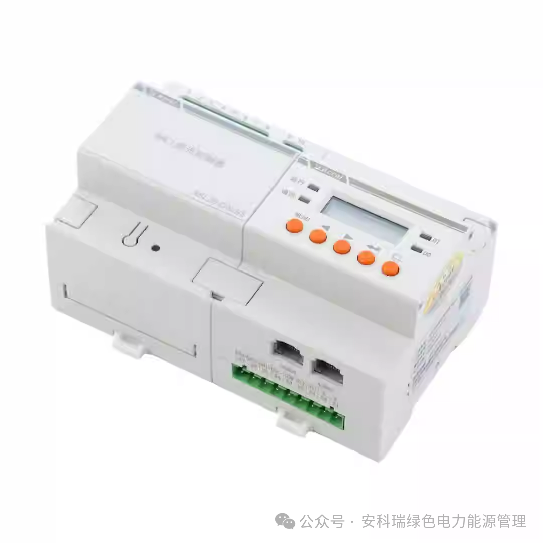
The core components of the Ankerui DALI system are clear and include DALI controllers, control panels, sensors, and touch screens. Coupled with dedicated upper computer software, it can achieve various control modes such as manual control, automatic sensing (e.g., human presence dimming), and remote monitoring, meeting the intelligent needs of different scenarios.
2. System Hardware and Cable Selection: Don’t Overlook These Details
A stable intelligent lighting system requires strict control from hardware selection to cable matching. The Ankerui DALI system has clear standards for hardware parameters and cable specifications, which directly relate to the stability of system operation.
1. Cable Selection: Different Buses, Choose the Right Cable
The DALI system involves two core buses—DALI bus and ALIBUS bus. The functions of the two are different, and the cable requirements also vary, as detailed in the table below:
| Bus Type | Recommended Cable Specification | Core Parameter Requirements | Applicable Scenarios |
|---|---|---|---|
| DALI Bus | ZR-BVV 2*1.5mm² | Bus voltage 16V, maximum voltage drop 2V; maximum distance between two farthest devices ≤300m; wire diameter must match length (≥0.5mm within 100m, ≥0.75mm for 100-150m, ≥1.5mm for over 150m) | Connect DALI controllers, drivers, and luminaires to achieve dimming and address communication |
| ALIBUS Bus | Cat5e or higher UTP pure copper network cable | Complies with IEC61156 standard, core wire diameter 0.5±0.01mm; must be routed through weak current bridge to avoid interference | Connect control panels, sensors, and touch screens to achieve control command transmission |
2. Hardware Load Capacity: Avoid Overloading to Prevent Failures
The load capacity of the DALI bus is strictly limited, which is key to the stable operation of the system:
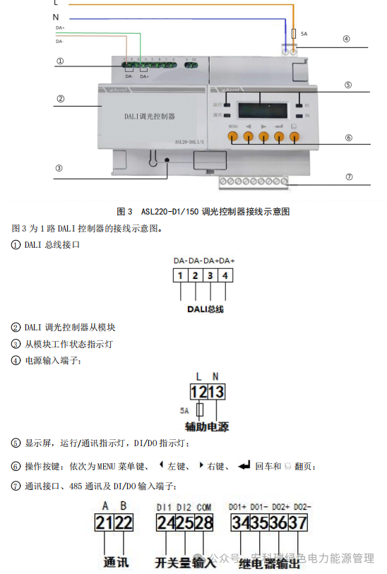
- A standard DALI bus supports a maximum of 64 independent addressable luminaires (maximum current per luminaire 2mA), and the total bus current must not exceed 250mA;
- The Ankerui DALI dimming controller has a rated current of 150mA, fully meeting the load requirements for 64 luminaires without the need for additional capacity expansion;
- If the number of luminaires exceeds 64 or the total current exceeds 250mA, it will lead to signal attenuation and communication failure of components, requiring subnet expansion through repeaters (supporting up to two levels of expansion).
3. Wiring Installation: Practical Points from Drawings to Site
Wiring installation is the core link for system implementation. The Ankerui DALI system has clear specifications for wiring methods and equipment installation locations, which must be accurately executed according to site conditions.
1. Core Wiring Principles: 3 Methods Allowed, 1 Absolutely Prohibited
Whether for the DALI bus or ALIBUS bus, the wiring methods support linear (daisy chain), star, and tree, but circular wiring is strictly prohibited (circular wiring can cause signal interference, leading to system failures). The specific wiring requirements are as follows:
- DALI Bus: No polarity distinction, directly connect to the DALI interface of the luminaire, can share conduits with power supply lines; control modules (controllers, panels, sensors) must be connected in a “daisy chain” manner, using extension network cable interfaces for branches;
- ALIBUS Bus: Preferably use “daisy chain” wiring, with a maximum distance of ≤200m between two devices on a single cable, total length of a single subnet bus ≤400m, and a maximum of 50 modules; if the number of panels/sensors is too high, auxiliary power supplies must be added (1 auxiliary power supply can support 50 panels/sensors).
2. Key Equipment Installation Specifications
- DALI Driver: Installed in the high-voltage distribution box, sufficient rail space must be reserved; connect to AC220V±10% voltage (ensure the power supply voltage meets requirements), all control circuit loads must be connected to the driver;
- Control Panel: Installed at a height of 1.3 meters from the ground, using a standard 86 bottom box, the opening size must match the panel; the back of the panel has two network ports for easy “daisy chain” connection, and the installation must ensure the arrow indicator points upwards;
- Distribution Box and Embedded Wiring: The number of conduits for wiring must be determined based on the number of circuits, clearly identify which distribution box belongs to which control circuit, and complete the conduit embedding in advance; before construction, modify the drawings according to the site and confirm accuracy before executing the wiring.
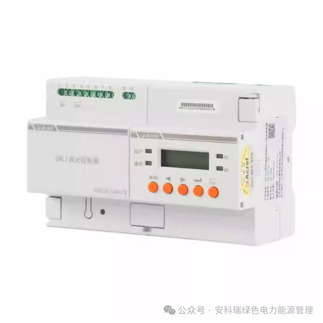
4. Debugging and Testing: Three Steps to Ensure Stable System Operation
After wiring is completed, a strict debugging process is required to verify system functionality and avoid operational failures later. The debugging of the Ankerui DALI system can be divided into three steps: “Power-on Testing, Address Allocation, Function Verification.”
1. Step One: Power-on Testing, Identify Basic Faults
After powering on, first observe the status of core devices to quickly locate basic issues:
- Luminaires: After powering on, they should switch to maximum brightness; if they do not light up, check for loose or short-circuited wiring;
- Controller: Observe the status of the indicator light; if the indicator light is abnormal (e.g., flashing error), check the power supply connection;
- Main module LCD screen: If it displays “Fault,” check for DALI bus short circuits; if it shows “Disconnected,” check the connection cap of the master-slave module or the status of the slave module; if it shows “Normal,” proceed to the next step.
2. Step Two: Address Allocation for Precise Control
DALI luminaires must be assigned independent addresses before they can be precisely controlled by the controller. The Ankerui system provides three address allocation methods to adapt to different scenarios:
- New Addressing: Delete all luminaire addresses on the bus and reassign them, suitable for the first debugging of a new system;
- Extended Addressing: Only assign addresses to unassigned luminaires without changing existing addresses, suitable for later addition of luminaires;
- Luminaire Registration: One-click scan of luminaires with assigned addresses, suitable for confirming luminaire status during system maintenance. (Note: If there are many luminaires on the bus, the addressing process may take several minutes, so please be patient.)
3. Step Three: Function Verification, Test Each Luminaire
After address allocation is complete, use the controller’s “One-Key Search Light” function to verify: the selected luminaire will flash between maximum and minimum brightness, allowing for confirmation of whether each luminaire can be controlled normally, avoiding “uncontrolled luminaires.”
Additionally, communication cables (especially the network cables for the ALIBUS bus) must be tested in advance: use a network cable tester to check the connectivity of the crystal head—non-shielded network cables should light up lamps 1-8 in sequence, while shielded network cables should light up lamp G in addition to lamps 1-8, ensuring there are no disconnections or miswirings in the network cable.
5. Conclusion: Core Advantages of the Ankerui DALI System
From technical features to practical implementation, the core competitiveness of the Ankerui DALI bus intelligent lighting system can be summarized in three points:
 Strong Compatibility: Adhering to the international DALI standard, devices from different brands can be interchanged, reducing later maintenance costs;
- Flexible Control: Independent addressing for each luminaire supports arbitrary group control, and scheme modifications do not require rewiring;
- Stable and Reliable: Clear load limits and standardized installation and debugging processes significantly reduce the probability of system failures.
Whether for new large public construction projects or retrofitting existing building lighting, the Ankerui DALI system can provide a full-process solution from hardware to software, helping to achieve the goals of “energy-saving, intelligent, and convenient” lighting management.


Scan the QR code to follow us
Technical Consultation:18321620761 (WeChat same number)
Business Consultation:13636483384 (WeChat same number)
Learn more electrical knowledge and Ankerui new product releases
Save the QR code, open Douyin and scan the search page
Douyin Number:22381882799
Douyin Name:Ankerui – Xiao Ji