Common input devices for PLCs include buttons, limit switches, proximity switches, toggle switches, dip switches, and various sensors, while output devices consist of relays, contactors, solenoid valves, etc. Correctly connecting the input and output circuits is essential for the safe and reliable operation of PLCs.
1. Connection between PLC and Main Control Devices
Figure 1 is a wiring diagram for input devices such as buttons, limit switches, and toggle switches. The PLC in the diagram uses a DC point-type input, meaning all input points share a common terminal COM, which also includes a DC24V power supply. If using grouped inputs, the method shown in the diagram below can be used for grouped connections.
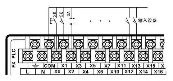
▲Figure 1 Connection between PLC and Main Control Input Devices
2. Connection between PLC and Rotary Encoders
A rotary encoder is a photoelectric rotary measurement device that directly converts the measured angular displacement into digital signals (high-speed pulse signals). Therefore, the output pulse signals from the rotary encoder can be directly input to the PLC, which can count the pulse signals using its high-speed counter to obtain measurement results. Different models of rotary encoders have different numbers of output pulses; some output A, B, and Z three-phase pulses, while others only output A and B phases, and the simplest ones only output A phase.
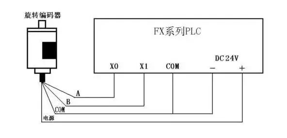
▲Figure 2 Connection between Rotary Encoder and PLC
As shown in Figure 2, this is a connection diagram between a two-phase pulse output rotary encoder and the FX series PLC. The encoder has four wires: two are pulse output wires, one is the COM wire, and one is the power wire. The encoder’s power supply can be an external power supply or directly use the PLC’s DC24V power supply. The “-” terminal of the power supply must be connected to the encoder’s COM terminal, while the “+” is connected to the encoder’s power terminal. The encoder’s COM terminal is connected to the PLC’s input COM terminal, and the A and B phase pulse output wires are directly connected to the PLC’s input terminals, taking care to note the PLC input’s response time. Some rotary encoders also come with a shield wire, which should be grounded when used.
3. Connection between PLC and Sensors
There are many types of sensors, each with different output methods. When using two-wire sensors such as proximity switches and photoelectric switches, due to the larger leakage current of the sensors, false input signals may occur, leading to erroneous PLC actions. In this case, a bypass resistor R can be connected in parallel at the PLC input, as shown in Figure 3. When the leakage current is less than 1mA, its impact can be ignored.
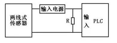
▲Figure 3 Connection between PLC and Two-Wire Sensors

Where: I is the leakage current of the sensor (mA), UOFF is the upper limit of the low-level input voltage of the PLC (V), and RC is the input impedance of the PLC (KΩ), with RC values varying based on different input points.
4. Connection between PLC and Multi-Position Dip Switches
If certain data in the PLC control system needs to be frequently modified, a multi-position dip switch can be used to connect to the PLC for external data setting. As shown in Figure 4, this is a schematic diagram of a single dip switch, which can input a decimal number from 0 to 9 or a hexadecimal number from 0 to F.
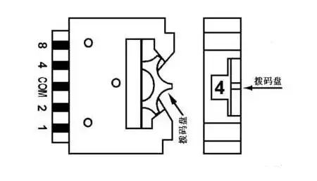
▲Figure 4 Schematic Diagram of a Single Dip Switch
As shown in Figure 5, four dip switches are assembled together, with the COM terminals of each dip switch connected together and connected to the COM terminal on the PLC input side. The four data wires of each dip switch are connected to the four input points on the PLC in a specific order. As seen in the diagram, using dip switches occupies many PLC input points, so this method is generally not adopted unless absolutely necessary.
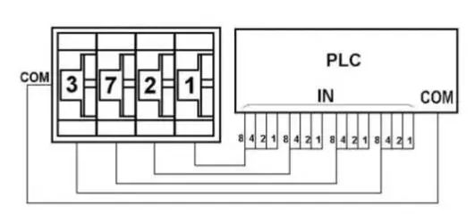
▲Figure 5 Connection between Four-Position Dip Switch and PLC
5. Connection between PLC and Output Device Switches
When connecting PLC to output devices, the voltage type and level of corresponding output devices (loads) can differ across different groups (different common terminals). However, the voltage type and level should be the same within the same group (same common terminal). The decision to group connections should be based on the voltage type and level of the output devices. As shown in Figure 6, the connection method between the PLC and output devices is illustrated using the FX2N as an example. The wiring shown assumes that the output devices have the same power supply, so the common terminals of each group are connected together; otherwise, they need to be grouped. The diagram only shows the connection of output points Y0-Y7 with the output devices, and the connection method for other output points is similar.
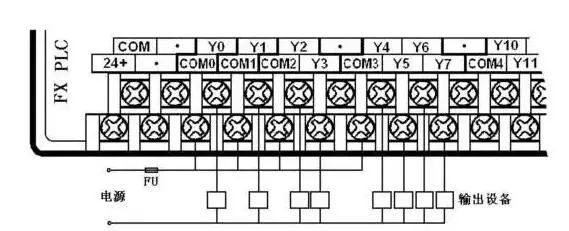
▲Figure 6 Connection between PLC and Output Devices
6. Connection between PLC and Inductive Loads
The output terminals of the PLC are often connected to inductive output devices (inductive loads). To suppress the voltage generated when the inductive circuit is opened, which could damage the internal output components of the PLC, when connecting PLC to inductive output devices, a flyback diode should be connected in parallel across the terminals if it’s a DC inductive load; if it’s an AC inductive load, a resistor-capacitor absorption circuit should be connected in parallel across the terminals, as shown in Figure 7.
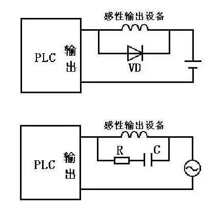
▲Figure 7 Connection between PLC and Inductive Output Devices
In the diagram, a flyback diode can be selected with a rated current of 1A and a rated voltage greater than three times the power supply voltage; the resistance value can be taken as 50~120Ω, and the capacitance value can be taken as 0.1~0.47μF, with the rated voltage of the capacitor being greater than the peak voltage of the power supply. When wiring, pay attention to the polarity of the flyback diode.
7. Connection between PLC and Seven-Segment LED Displays
PLC can be directly connected to seven-segment LED displays using switch outputs, but if the PLC controls a multi-digit LED seven-segment display, a significant number of output points will be required.
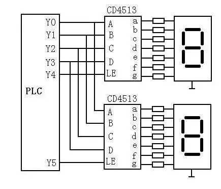
▲Figure 8 Connection between PLC and Two-Digit Seven-Segment LED Display
As shown in Figure 8, in the circuit, a chip CD4513 with latching, decoding, and driving functions is used to drive a common cathode LED seven-segment display. The data input terminals A to D of two CD4513 chips share the four output points of the PLC, where A is the least significant bit and D is the most significant bit. LE is the latch enable input terminal, which, on the rising edge of the LE signal, latches the BCD number input from the data input terminals into the internal registers of the chip and displays the number after decoding. If the input is not a decimal number, the display will turn off. When LE is high, the displayed number is unaffected by the data input signal. Clearly, the number of output points occupied by N displays is P=4+N.
If the PLC uses relay output modules, a pull-down resistor should be connected to each output terminal connected to the CD4513 to avoid floating inputs at the CD4513 when the output relay contacts open. When the state of the PLC output relay changes, its contacts may bounce, so data output signals should be sent first, and after the signal stabilizes, the data should be latched into the CD4513 using the rising edge of the LE signal.

Disclaimer: This article is reprinted from the internet, and the copyright belongs to the original author. If there are copyright issues, please contact us for deletion. Thank you!