Today, I will share with you the content about PLC, giving you a simple introduction to PLC. I will briefly introduce the following five points.
1. First, let’s talk about what a control system and a controller are.
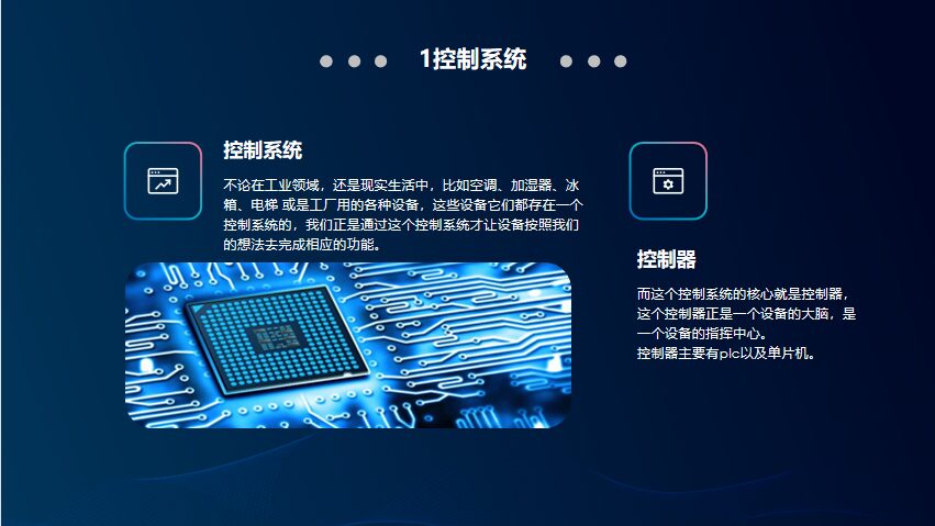
Whether in the industrial field or in real life, such as air conditioners, humidifiers, refrigerators, elevators, or various equipment used in factories, these devices all have a control system. It is through this control system that we allow the devices to perform their functions according to our intentions.
The core of this control system is the controller, which is the brain of the device, the command center of the device. The main types of controllers are PLC and microcontrollers.
2. Collaboration of PLC Software and Hardware
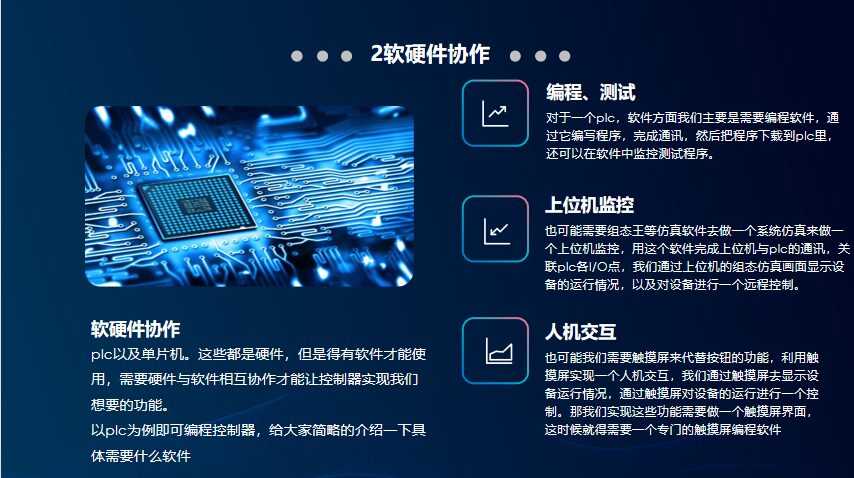
PLC and microcontrollers are hardware, but they need software to function. The hardware and software must collaborate to enable the controller to achieve the desired functionality. Taking PLC as an example, we need programming software to program the controller, and I will briefly introduce what software is specifically needed. For a PLC, we mainly need programming software to write programs, complete communication, and then download the program to the PLC, and we can also monitor and test the program within the software.
Upper Computer Monitoring: You may also need simulation software like Kingview for system simulation to perform upper computer monitoring. This software completes communication between the upper computer and PLC, associates with the I/O points of the PLC, and displays the operational status of the device through the simulation interface, allowing for remote control of the device.
Human-Machine Interaction: We may also need a touch screen to replace the function of buttons, using the touch screen to achieve human-machine interaction. We display the operational status of the device through the touch screen and control the operation of the device via the touch screen. To achieve these functions, we need to create a touch screen interface, which requires a specialized touch screen programming software.

The image shows a simulation interface created using Kingview. Just take a brief look at these images.
The upper computer refers to a computer that can directly issue control commands. By installing simulation software on the upper computer, we can directly control the device. For example, the buttons in the pink area of the image are associated with the input points of each PLC. By clicking the corresponding position in the software, we can achieve the same effect as pressing the physical buttons that need to be wired.
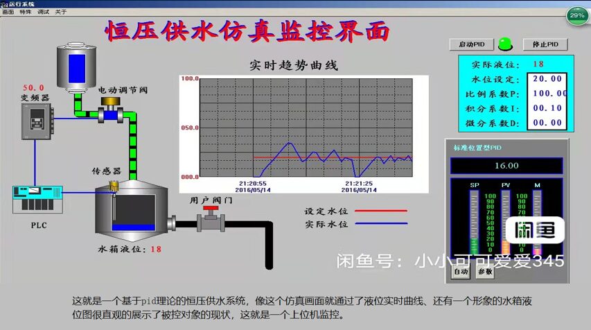
This is a constant pressure water supply system based on PID theory. The simulation interface displays the real-time curve of the liquid level and an intuitive water tank level diagram, showcasing the current status of the controlled object, which is upper computer monitoring.
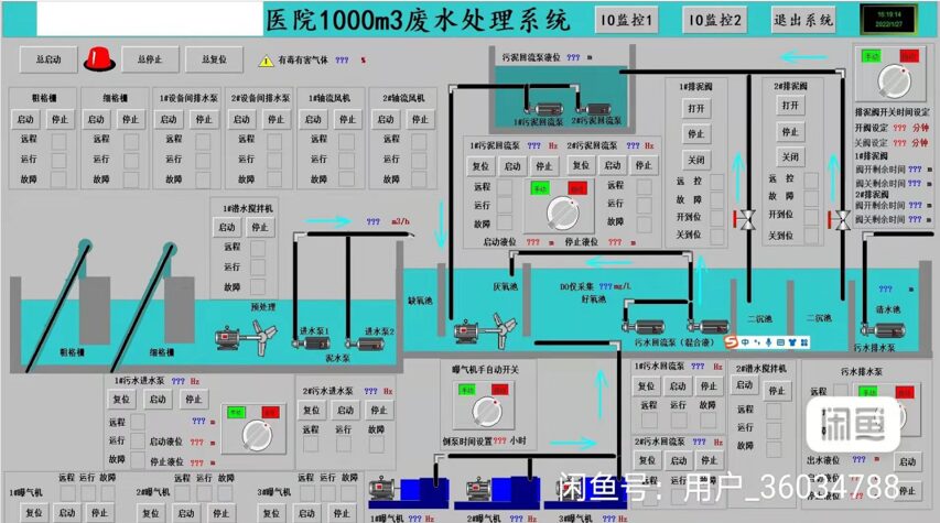
For example, this wastewater treatment system has a more complicated operational mechanism, so the simulation diagram appears more complex and professional.
3. Characteristics of Controllers and Application Field Division
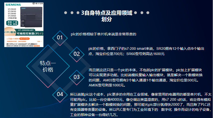
Characteristic 1: Price
Compared to microcontrollers, the price of PLCs is very expensive. Taking Siemens S7-200 Smart as an example, the SR20 model has 12 input points/8 output points, priced at 700 yuan on Taobao; the SR60 model can reach 1600 yuan.
This is just the cost of the PLC itself, excluding the expansion modules. Adding expansion modules to the PLC can achieve more functions. For instance, an analog input/output module solves the issue of digital-analog conversion; the AM03 model has 2 input channels and 1 output channel, priced at 500 yuan, while the AM06 model costs 1000 yuan.
Thus, regarding the cost of PLCs, they are more commonly used in industrial fields, while household appliances typically use microcontrollers. For example, an air conditioner priced at 4000 yuan would require an analog expansion module to solve the digital-analog conversion problem if using S7-200; the PLC portion alone could cost nearly 2000 yuan, and besides the PLC, there are also expensive devices like inverters. Therefore, PLCs are electronic devices designed specifically for digital operations in industrial environments, where a single device can cost tens of thousands.
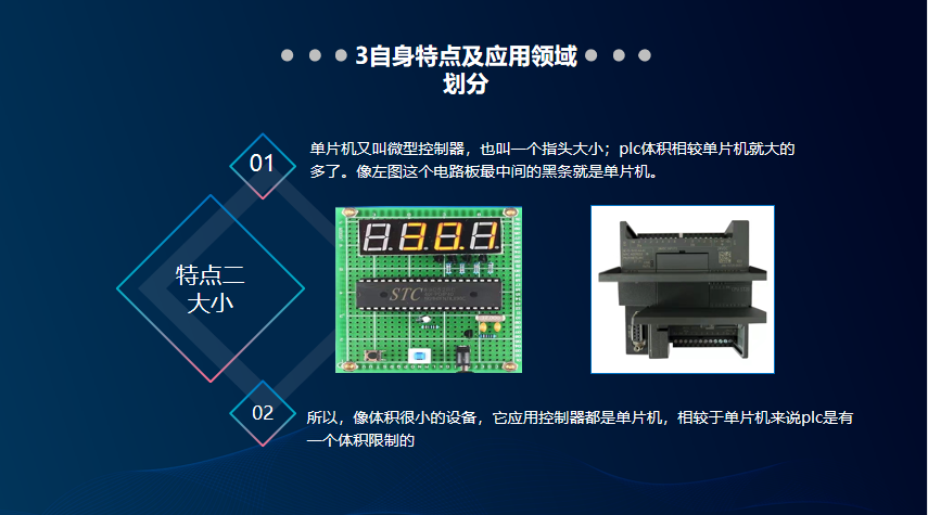
Characteristic 2: Size
Microcontrollers, also known as microcontrollers, are about the size of a finger; PLCs are significantly larger in comparison. The black strip in the center of the circuit board in the left image is the microcontroller.
Therefore, for devices with very small sizes, microcontrollers are used, whereas PLCs have size limitations.
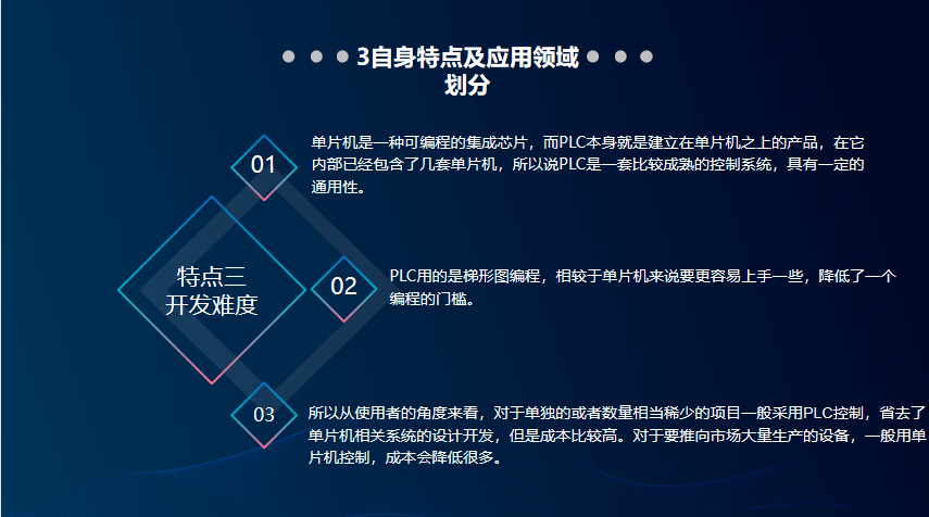
Characteristic 3: Development Difficulty
Microcontrollers are programmable integrated chips, while PLCs are products built on microcontrollers and contain several microcontrollers internally. Therefore, PLCs are relatively mature control systems with a certain degree of universality.
PLCs use ladder diagram programming, which is easier to grasp compared to microcontrollers, lowering the programming threshold.
From the user’s perspective, for isolated or relatively rare projects, PLC control is generally adopted, saving the design and development of microcontroller-related systems, but at a higher cost. For devices aimed at mass production, microcontrollers are typically used to significantly reduce costs.
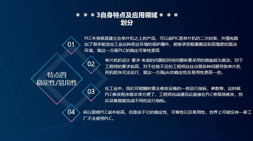
Characteristic 4: Stability, Reliability, and Usability
PLCs are built on microcontrollers, which means they are a second encapsulation of microcontrollers. The peripheral circuits include many protective components that can adapt to harsh industrial conditions, allowing them to withstand rough handling and high-intensity vibration environments, thus providing higher stability and reliability.
Microcontroller design involves complex considerations and measures, requiring higher qualifications from engineers. Inexperienced engineers often encounter various issues leading to microcontroller crashes, whereas PLCs offer higher stability and usability.
In industrial settings, we may need to modify the operating parameters of devices at any time. In this case, modifying the PLC program is very convenient, allowing engineers to make changes directly on-site next to the PLC, enabling the device to meet different operational parameters.
Therefore, even though PLCs are costly, their stability, reliability, and usability make them indispensable in industrial settings.
4. Now, let’s discuss the hardware components of PLCs.
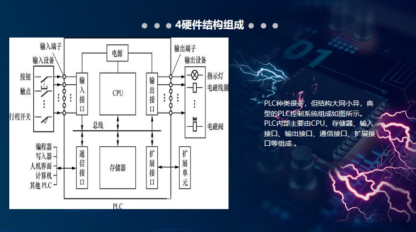
There are many types of PLCs, but the structures are largely similar. A typical PLC control system consists of the following components: CPU, memory, input interface, output interface, communication interface, and expansion interface.
CPU:
The CPU, also known as the central processing unit, is the control center of the PLC. It connects with memory and various interfaces to ensure they operate in an orderly manner. The performance of the CPU significantly impacts the speed and efficiency of PLC operations.
Its specific functions include: receiving programs and information sent from communication interfaces and storing them in memory; continuously detecting the status information sent from input interfaces using a scanning method to determine the status of input devices.
Thirdly, it executes the programs stored in memory line by line from top to bottom, performs various calculations, stores the results, and then controls output devices through the output interface.
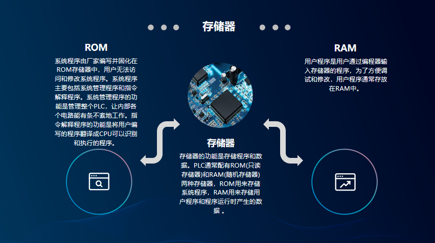
Memory:
The function of memory is to store programs and data. PLCs typically come with two types of memory: ROM (Read-Only Memory) and RAM (Random Access Memory). ROM is used to store system programs, while RAM is used to store user programs and data generated during program execution.
The system program is written by the manufacturer and is fixed in the ROM, which users cannot access or modify. The system program mainly includes the system management program and instruction interpretation program. The function of the system management program is to manage the entire PLC, ensuring that all internal circuits operate in an orderly manner.
The function of the instruction interpretation program is to translate the user-written programs into a format that the CPU can recognize and execute. User programs are the programs input into memory by users through a programmer, and for debugging and modification convenience, user programs are usually stored in RAM.
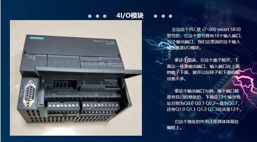
I/O Modules
The PLC on the left is the S7-200 Smart SR30 model, which has 18 input ports and 12 output ports. When we refer to input and output, we are talking about I/O modules.
In this image, when the lid is opened, the row below is the output ports, while the input ports are under the lid above, which look similar to the output ports when opened. Taking this output port as an example, each port has its own address. The 12 output addresses here are Q0.0, Q0.1, Q0.2 up to Q0.7, and also Q1.0, Q1.1, Q1.2, and Q1.3, totaling 12. The significance of these addresses is reflected in programming.
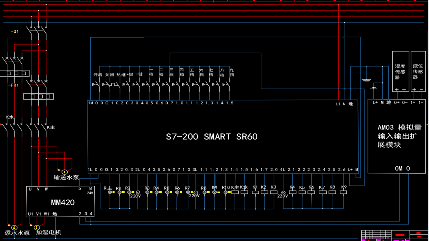
For instance, this is a CAD diagram of an industrial humidifier. Except for the normally open thermal relay contact, all the buttons in the top row are connected to the input ports.
For example, if you press the button located at position I0.5 for the first gear, during the time the button is pressed, the I0.5 input port will be powered. What happens after this input port is powered?
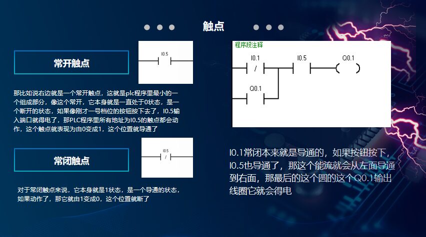
For example, the right side shows a normally open contact, which is the smallest component in the PLC program. This normally open contact is always in a state of 0, which is an open state. If the button for the first gear is pressed, the I0.5 input port will be powered, and all contacts in the PLC program with the address I0.5 will act, causing this contact to change from 0 to 1, closing the circuit. For normally closed contacts, they are in a state of 1, meaning they are closed. If activated, they change from 1 to 0, opening the circuit.
I0.1 is normally closed and is originally conductive. If the button is pressed, and I0.5 is powered, the current will flow from the left to the right, energizing the circular Q0.1 output coil, causing the output port Q0.1 to be powered, and thus the connected light bulb will light up.
5. Self-Locking and Interlocking Structure:
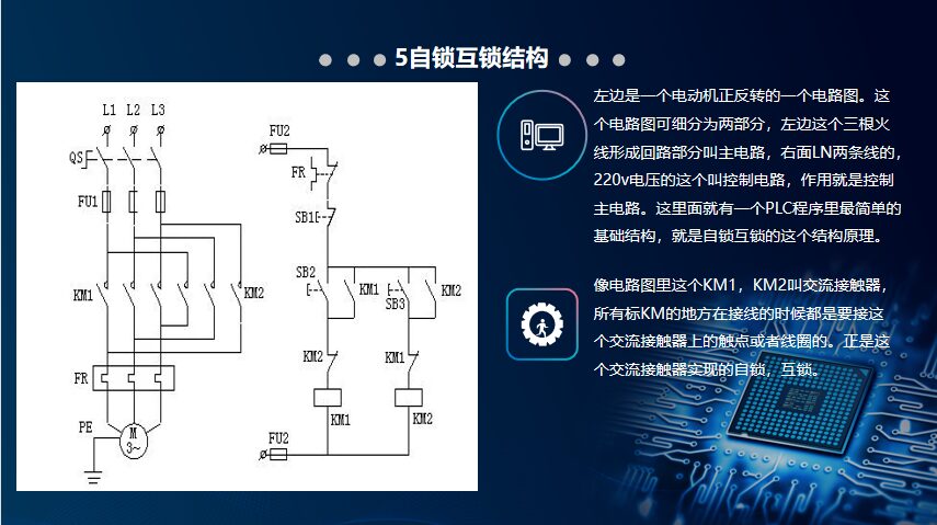
On the left is a circuit diagram for a motor’s forward and reverse rotation. This circuit diagram can be divided into two parts: the left part with three live wires forms the main circuit, while the right part with lines LN represents the control circuit, which controls the main circuit. Here we have the simplest basic structure in the PLC program, which is the self-locking and interlocking structure principle.
In the circuit diagram, KM1 and KM2 are AC contactors. All points marked KM are connected to the contacts or coils of the AC contactor during wiring. It is this AC contactor that achieves self-locking and interlocking.
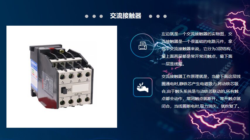
Let’s discuss this AC contactor: the left image shows a physical AC contactor. It is a very basic circuit component, consisting of three layers: the top two layers are normally open and normally closed contacts, while the bottom layer is the coil.
The working principle of the AC contactor is that when the coil at the bottom layer is powered, the static iron core generates electromagnetic attraction, pulling the moving iron core, causing the contact system linked to the moving iron core to act. The normally closed contacts open while the normally open contacts close. When the coil is de-energized, the attraction disappears, and the system resets.

In this circuit diagram, there are two AC contactors, KM1 and KM2. The left main circuit at 380V is called the main circuit contact point KM1. After the fuse FU is connected, it should connect to the normally open contact in the middle layer of the AC contactor. The two boxes at the bottom of the control circuit represent the coils of the AC contactors, while the other KM1 is the auxiliary circuit contact point connected to the top layer.

When I press the SB2 button, during the time it is pressed, SB2 closes, and the KM1 coil (the two boxes at the bottom) is powered, allowing KM1 in the main circuit to close, and the motor can run. However, if I release SB2, it will open, and everything will stop, demonstrating the self-locking structure’s function.
As long as I press the SB2 button, as long as the KM1 coil is powered, the KM1 auxiliary contact will close, allowing power to flow, so even if I release the start button, the motor will continue to run; this is self-locking.
The motor is now running, and I want to change its rotation direction. To make the motor rotate in reverse, I press the SB3 button, which powers the KM2 coil, causing the normally closed contact in the control circuit of KM2 to open, breaking the KM1 coil circuit. This is called interlocking.
The main circuit KM1 is now disconnected, and KM2 is closed, changing the phase sequence of the three-phase AC power L1, L2, and L3, achieving forward and reverse rotation.

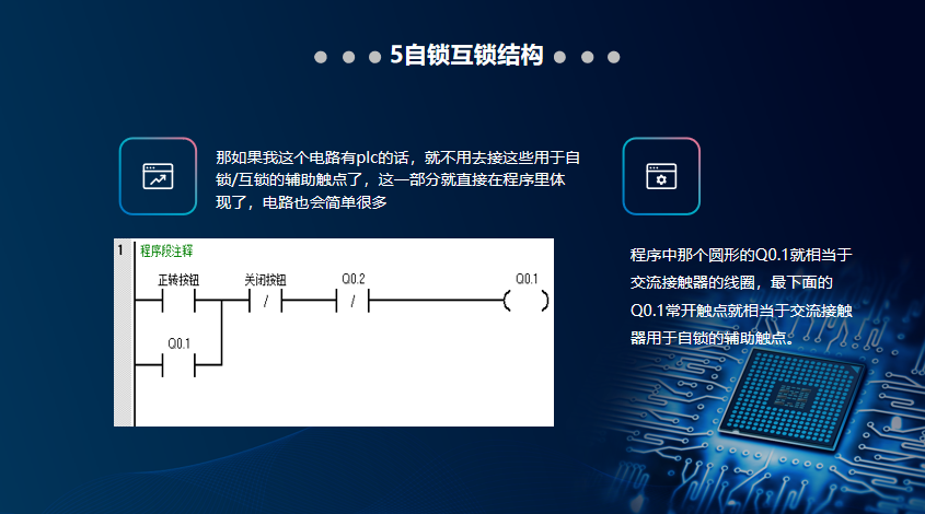
If this circuit had a PLC, there would be no need to connect these auxiliary contacts for self-locking/interlocking; this part could be directly reflected in the program, simplifying the circuit. The circular Q0.1 in the program corresponds to the coil of the AC contactor, and the normally open contact Q0.1 at the bottom corresponds to the auxiliary contact used for self-locking.
PLC, or Programmable Logic Controller, is an automation device that serves as the core of automation. Its characteristics make it an essential device in the industry, an indispensable part of industrial operations.
Editor: Zhang Yuehan

Inspection | Information | Technology
Let us move forward together
Stay determined
Remember, this is a warm public account