
Today, I will explain the Siemens S7-200 series PLC logic instructions, as well as its programming methods and the structural rules of ladder diagram programming, to help new users who want to quickly get started with PLC learn the key points of these methods. Let’s take a look at this sharing!
1. Bit Logic Instructions
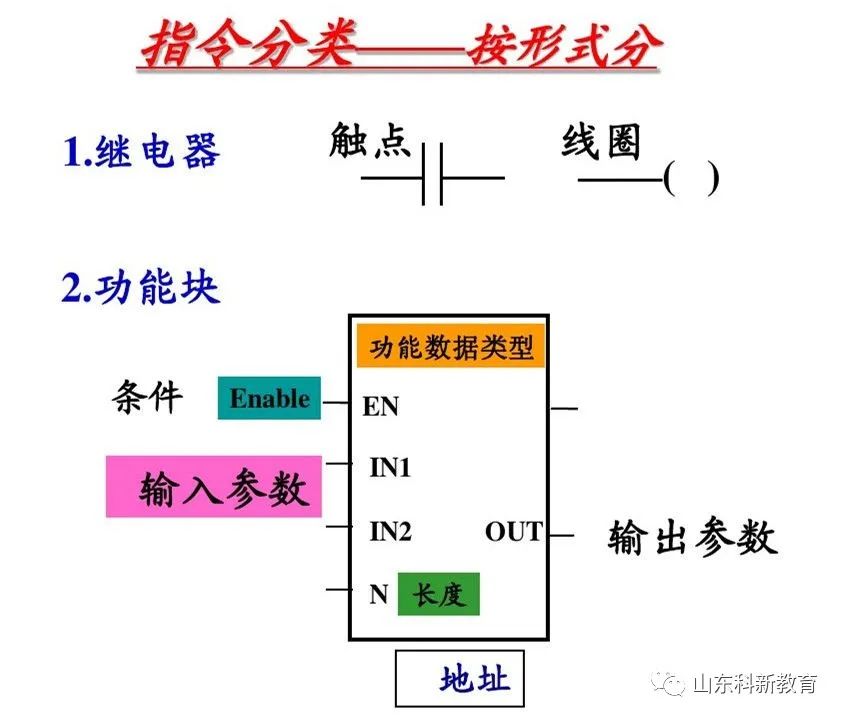
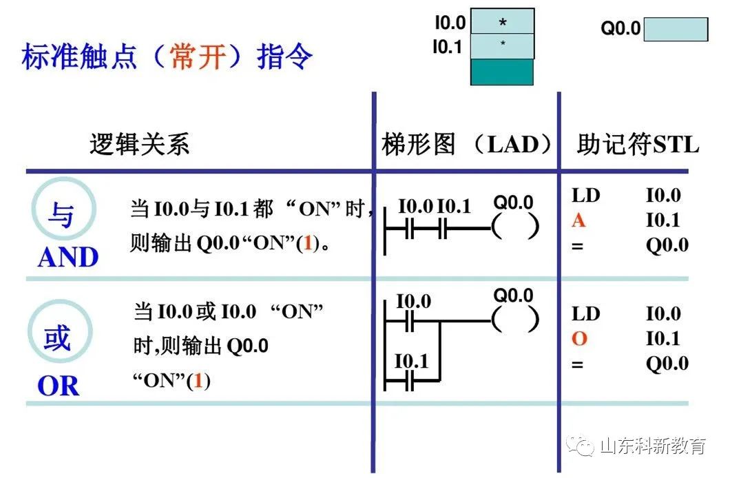
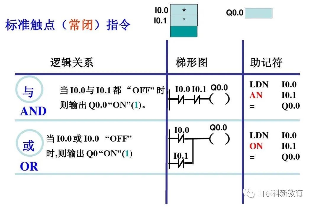
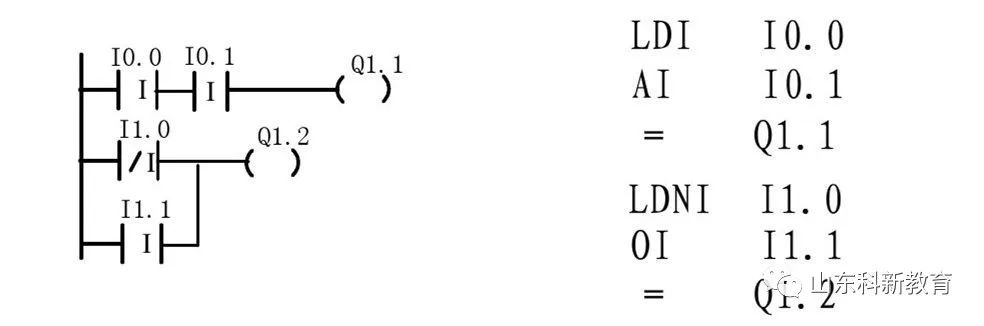
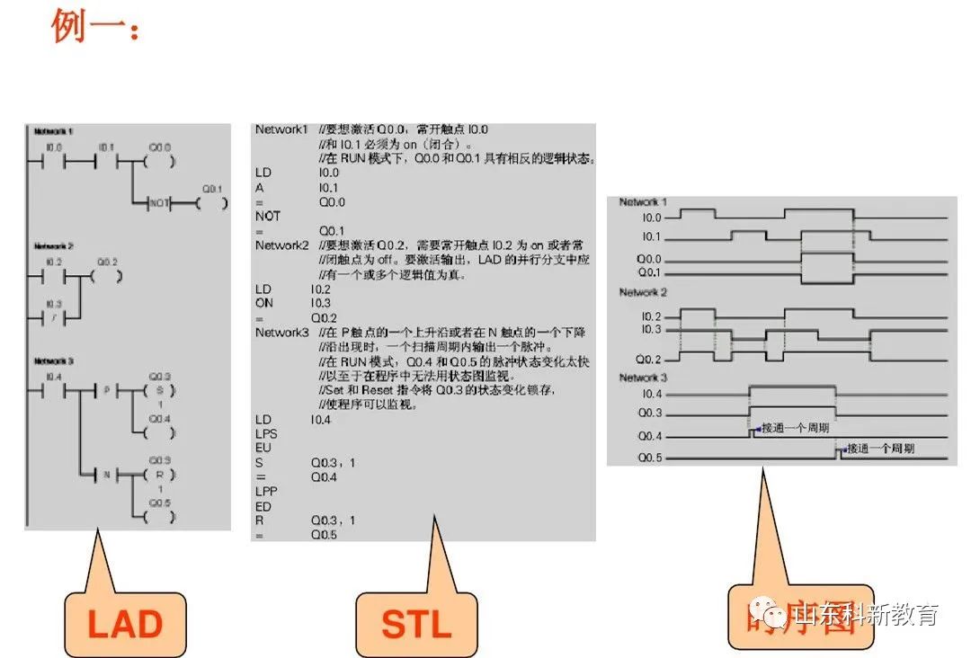
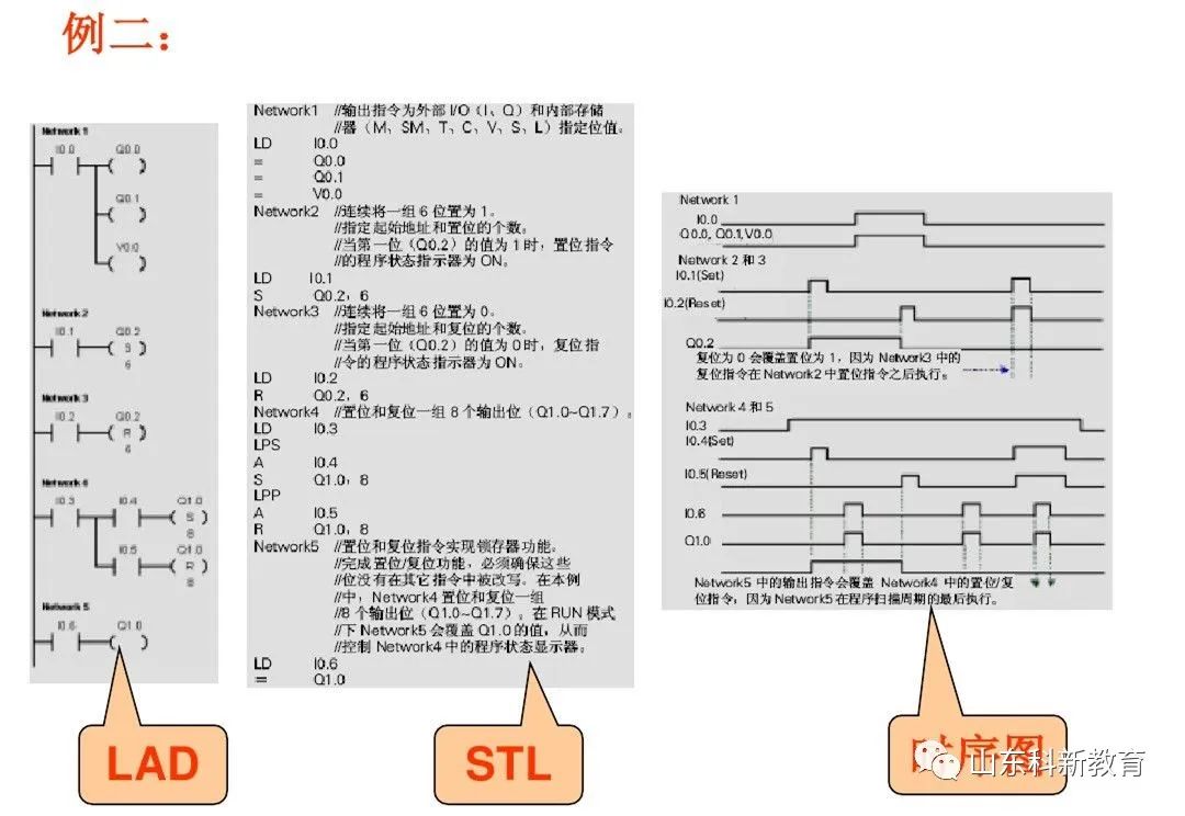
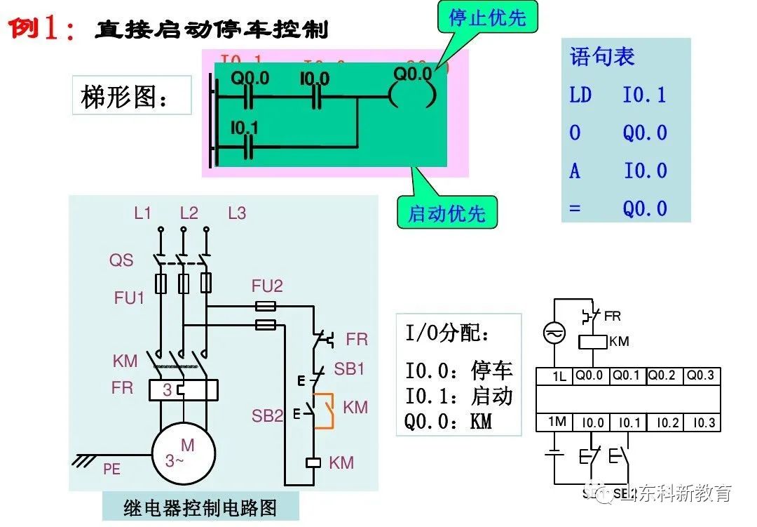
(1) Contact and Coil Instructions
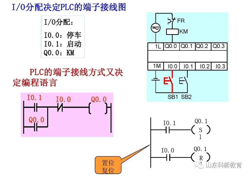
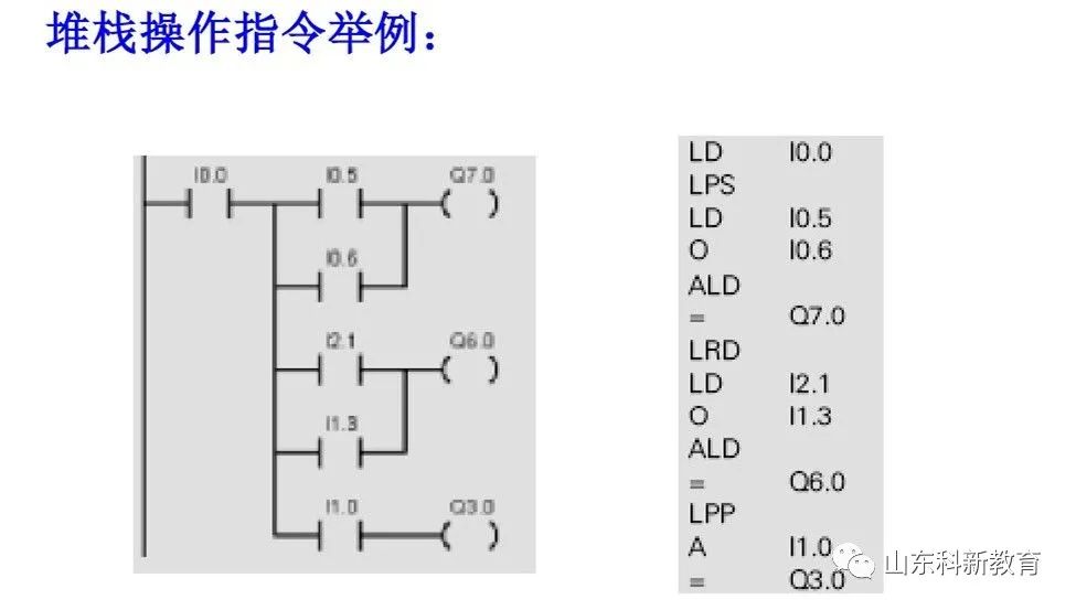
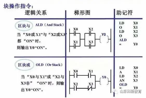
The programming principles of PLC ladder diagram language:
1. A ladder diagram consists of multiple rungs, each coil can form a rung, and each rung has multiple branches, with each rung representing a logical equation;
2. The relays, contacts, and coils in the ladder diagram are not physical; they are bits in the PLC memory (1 = 0N; 0 = 0FF); during programming, normally open/normally closed contacts can be referenced infinitely, while coil outputs can only be referenced once;
3. The flow in the ladder diagram is not physical current but “conceptual current,” which can only flow from left to right;
4. The calculations of the user program are based on the contents of the PLC’s input/output image registers, and the results of logical operations can be immediately used by subsequent programs;
5. Internal relays of the PLC cannot be used for control; they can only store intermediate states of logical control;
6. Output coils cannot directly drive field actuators; they must drive through power devices on I/O modules.
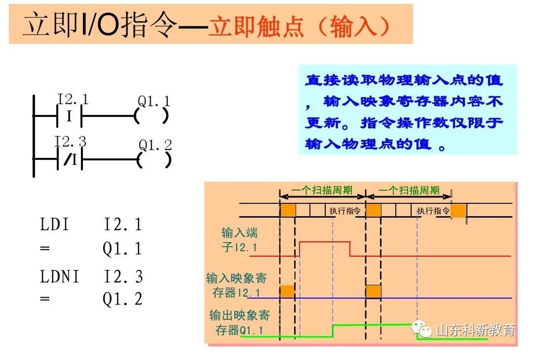
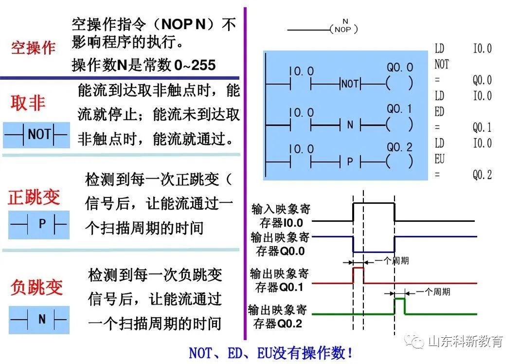
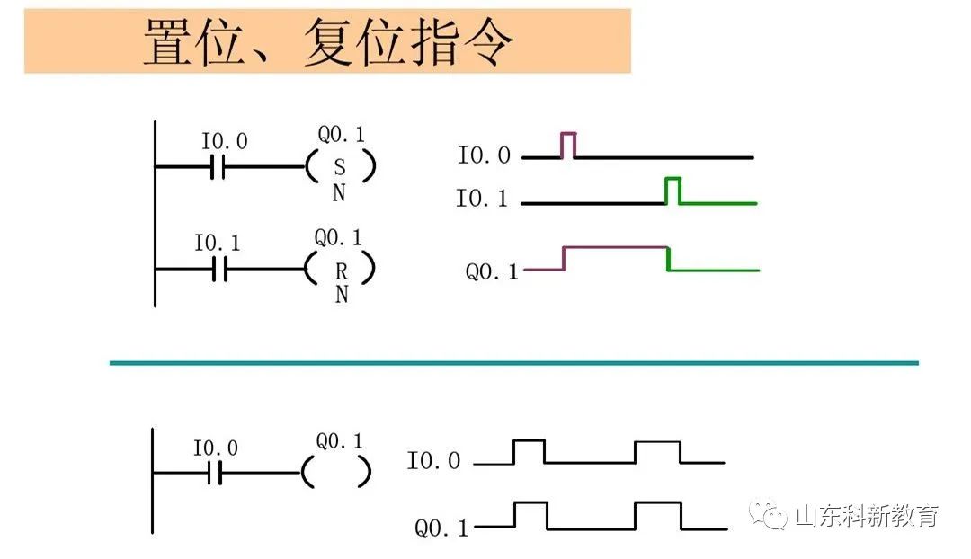
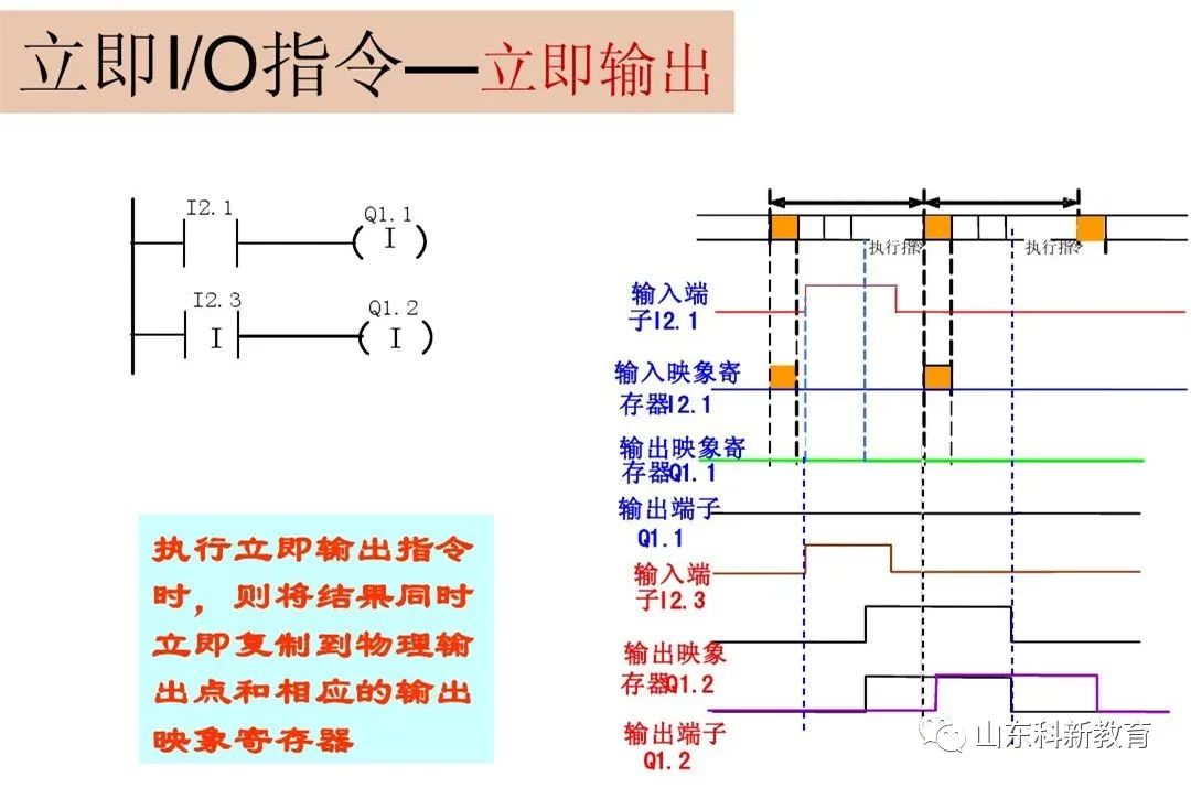
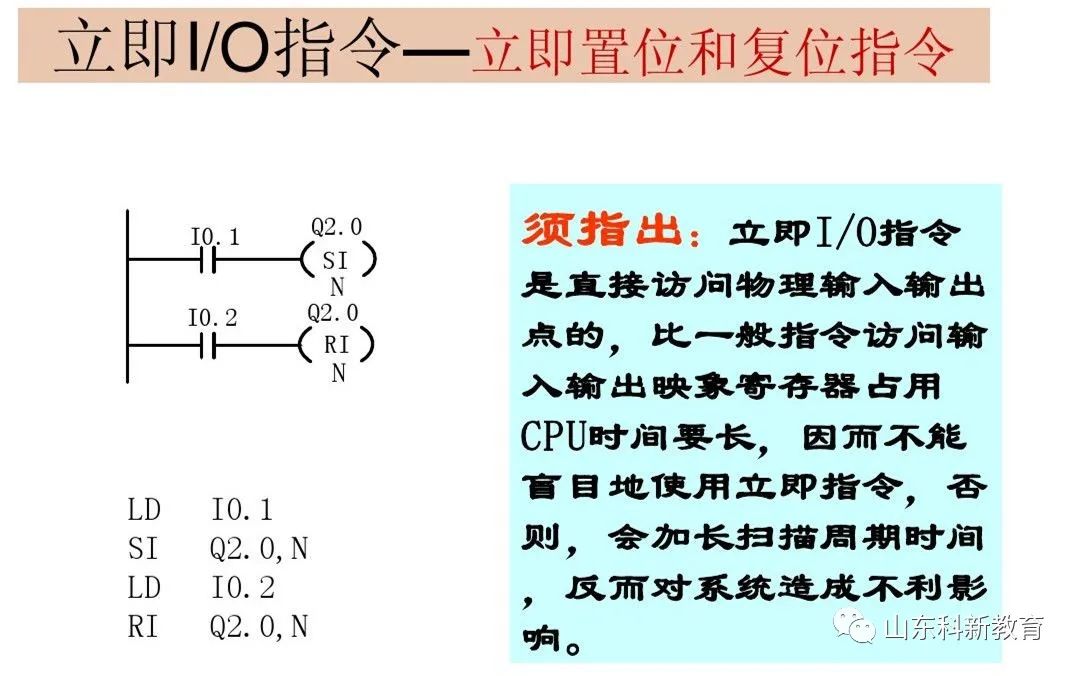
The basic logic instructions are mainly focused on bit logic operations. In the bit logic instructions, unless otherwise specified, the effective area of operands is: I, Q, M, SM, T, C, V, S, L, and the data type is BOOL. Contact and coil instructions can be divided into: standard instructions, immediate instructions, negation instructions, and positive (negative) edge instructions.
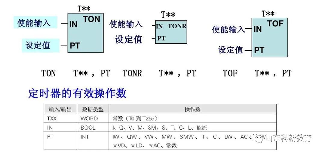
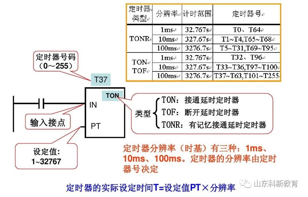
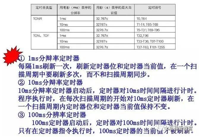
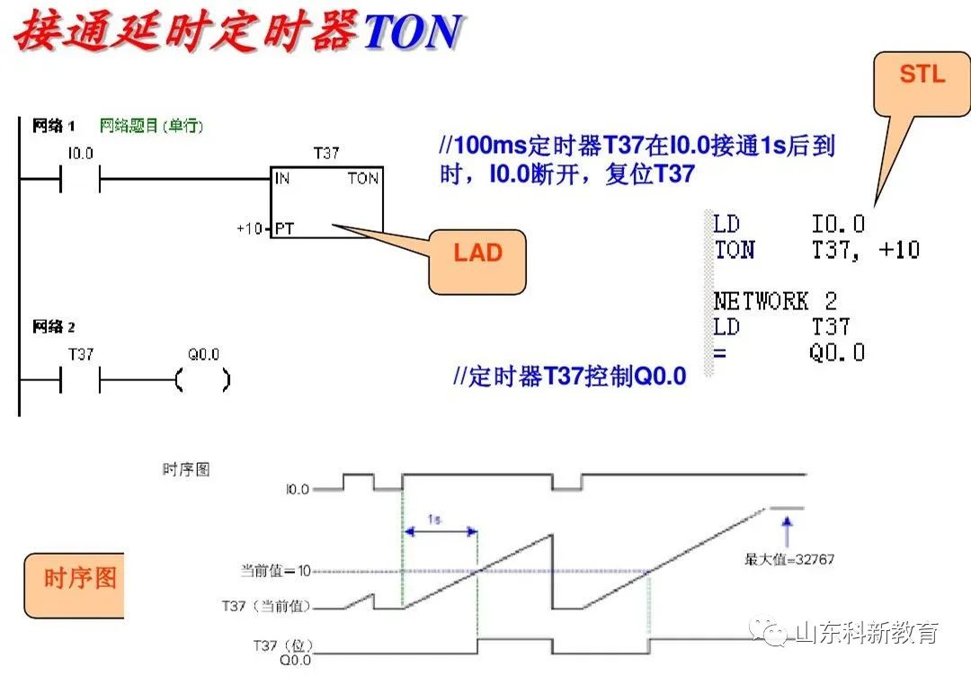
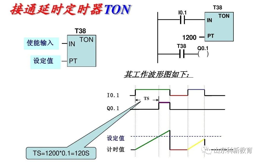
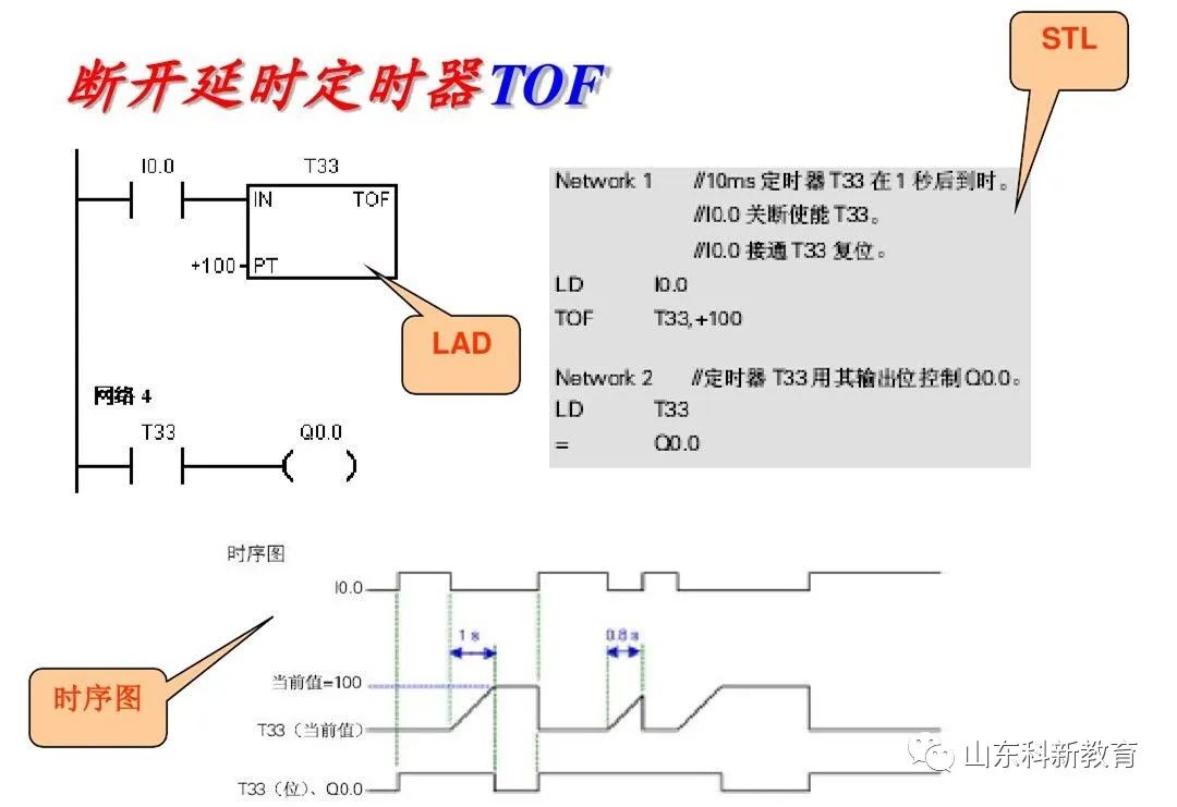
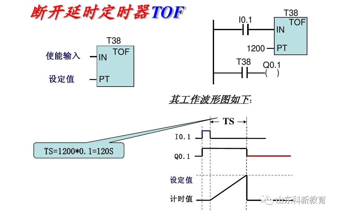
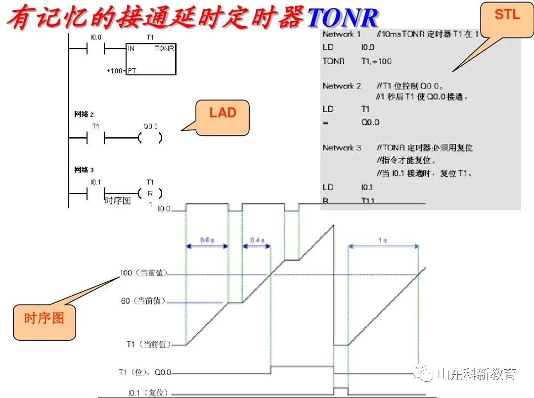
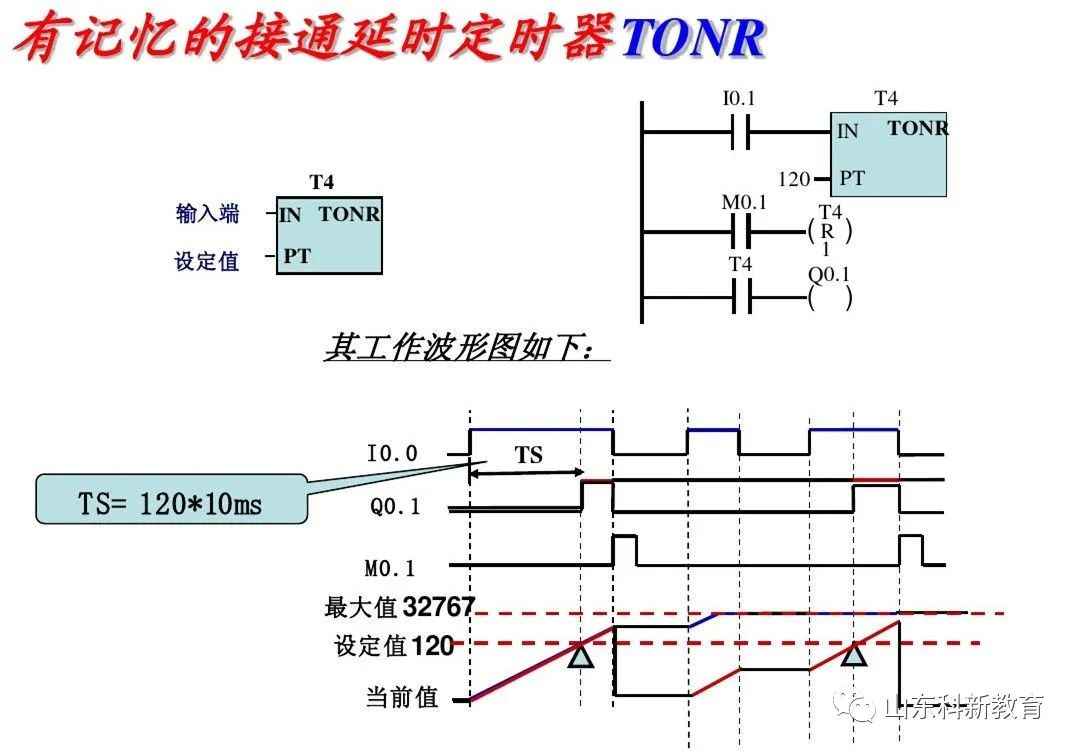
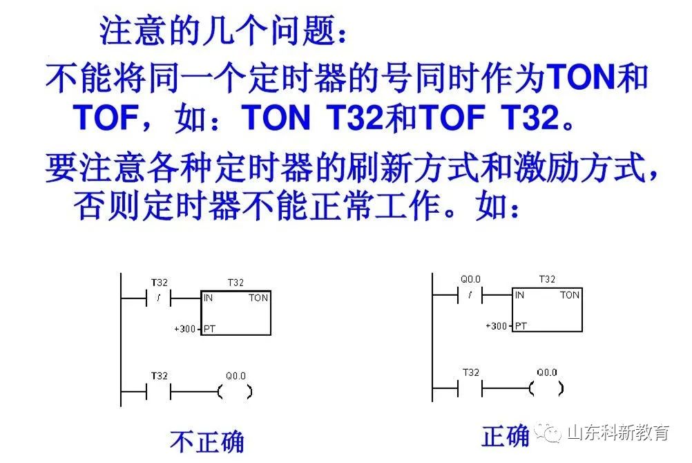
2. Timer Instructions
Includes: On-delay timer (TON), memory on-delay (retentive) timer (TONR), off-delay timer (TOF). The S7-200 has 256 timers (T0~T255).
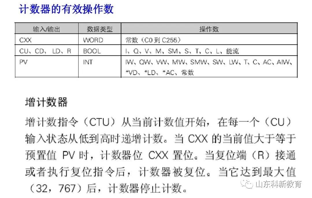
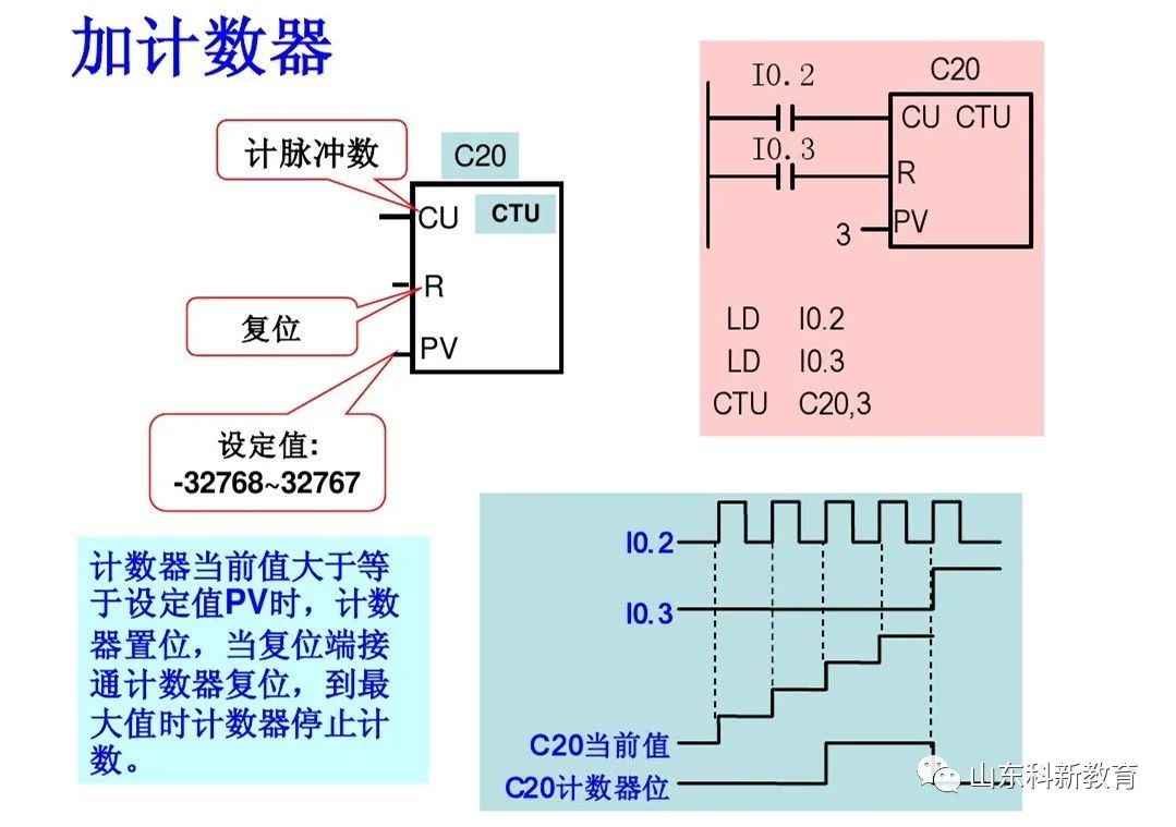
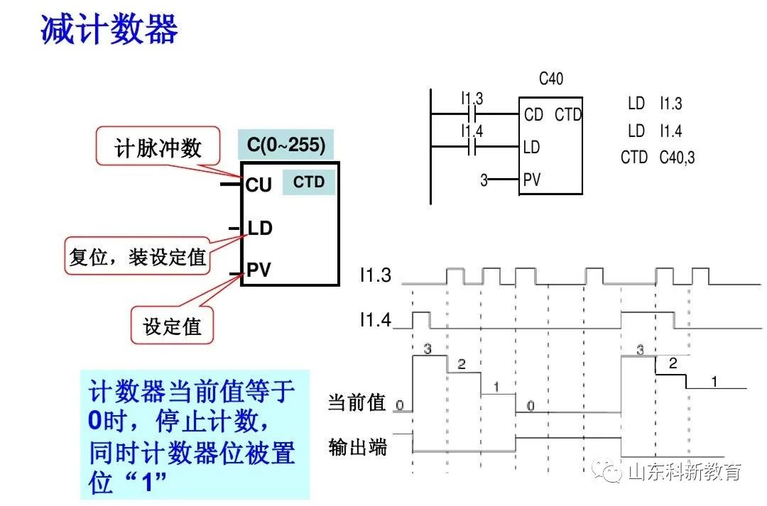
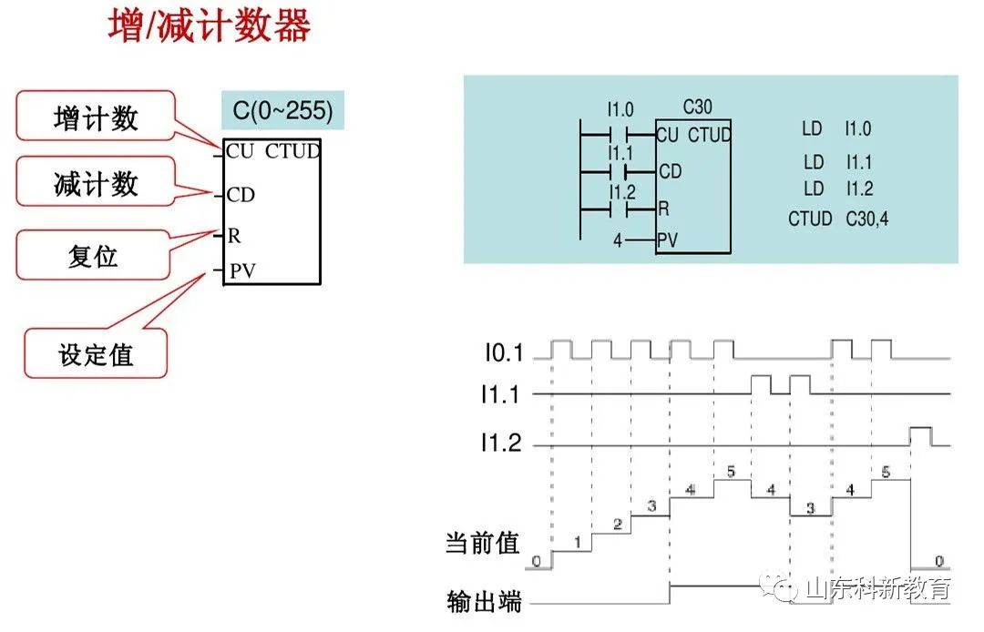
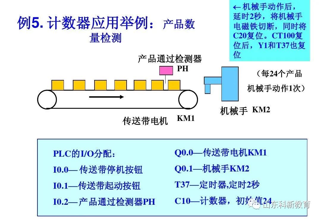
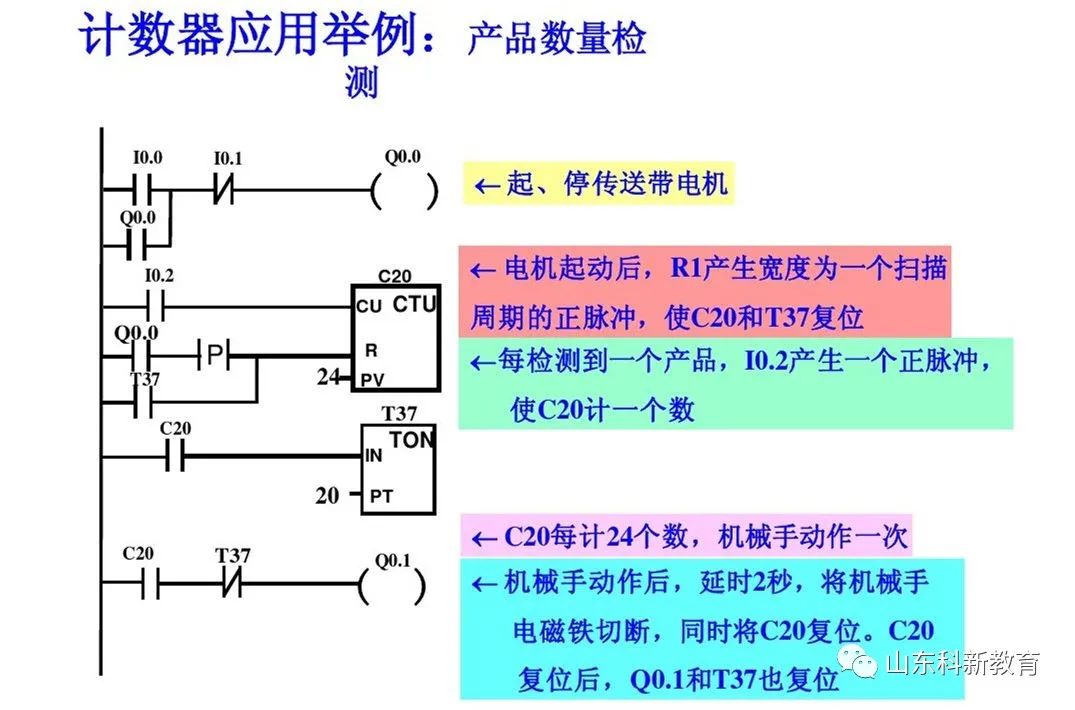
3. Counter Instructions
Includes: Count Up (CTU), Count Down (CTD), and Count Up/Down (CTUD) with a total of 256 (C0~C255). Counters count the internal clock pulses of the PLC, while counters also count external or program-generated count pulses. The current value of accumulated counts (16-bit signed integer) is stored in the 16-bit current value register of the counter. Each counter has only one address for the 16-bit current value register. In a program, do not reuse the same counter number, and do not allocate it to several different types of counters.
Source: This article is reprinted from the internet, and the copyright belongs to the original author. If there are copyright issues regarding the work, please contact us in time for deletion. Thank you!

Scan to Follow
WeChat ID|13615417996
Follow the QR code on the left to get free access to
【Siemens Data Collection】