
1. What is PLC?
PLC is an intelligent controller, full name is Programmable Logic Controller.
The definition of PLC is: an electronic system designed for digital operation, specifically for use in industrial environments. It uses a type of programmable memory for internal storage of programs, executing logical operations, sequential control, timing, counting, and arithmetic operations, and controls various types of machinery or production processes through digital or analog input/output. PLC and its related peripheral devices should be designed to integrate easily with industrial control and to facilitate functionality expansion.

2. Characteristics of PLC (Advantages)
High reliability and strong anti-interference capability
Comprehensive functionality, well-equipped, and highly applicable
Easy to learn and simple to operate
System design, easy maintenance, easy modification, and simple construction
Compact size, lightweight, and low power consumption

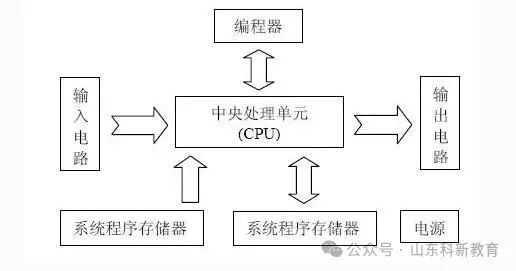
3. Structure of PLC and Functions of Each Part
The structure of programmable controllers varies, but the general principle of their composition is essentially the same, all centered around a microprocessor. Typically, it consists of a Central Processing Unit (CPU), memory (RAM, ROM), Input/Output units (I/O), power supply, and programmer.

Central Processing Unit (CPU)
The CPU, as the core of the entire PLC, plays the role of the overall commander. The CPU generally consists of a control circuit, arithmetic unit, and registers, all of which are usually encapsulated in an integrated circuit chip.
The CPU connects to the memory unit and input/output interface circuits through address, data, and control buses. The functions of the CPU include: reading instructions from memory, executing instructions, fetching the next instruction, and processing interrupts.

Memory (RAM, ROM)
The memory is mainly used to store system programs, user programs, and working data. The memory that stores system software is called system program memory, the memory that stores application software is called user program memory, and the memory that stores working data is called data memory.
Commonly used memories include RAM, EPROM, and EEPROM. RAM is a type of read-write random access memory used to store user programs, generating a user data area, which can be easily modified. RAM memory is a high-density, low-power, and inexpensive semiconductor memory that can use a lithium battery as a backup power source. It can effectively retain stored information during power outages. EPROM and EEPROM are types of read-only memory. These types of memory are used to solidify system management programs and application programs.

Input/Output Unit (I/O Unit)
The I/O unit is essentially the interface component for transmitting input and output signals between the PLC and the controlled object. The I/O unit has good electrical isolation and filtering functions; the input devices connected to the PLC input interface include various switches, buttons, sensors, etc., while the output control devices of the PLC are often solenoids, contactors, and relays, which can be AC or DC types, high voltage or low voltage types, voltage types or current types.

Power Supply
The PLC power supply unit includes the system power supply and backup battery, and its function is to convert the external power supply into internal working voltage. The PLC has a regulated power supply to provide power to the CPU unit and I/O unit.

Programmer
The programmer is the most important peripheral device of the PLC. It is used to send user programs into the PLC’s memory, and it can also check, modify programs, and monitor the PLC’s working status. In addition, by adding appropriate hardware interfaces and software packages to a personal computer, it can be used to program the PLC. Using a microcomputer as a programmer, ladder diagrams can be directly compiled and displayed.

4. Working Principle of PLC
PLC operates in a cyclic scanning manner, where the user program is stored sequentially in the PLC. The CPU starts executing the program from the first instruction until it encounters an end symbol, then returns to the first instruction, and this cycle continues indefinitely. The scanning process of the PLC consists of several stages: internal processing, communication operations, program input processing, program execution, and program output. The time required to scan the entire process once is called the scan cycle. When the PLC is in a stop state, only internal processing and communication operations are performed. When the PLC is in an operational state, it continuously cycles through internal processing, communication operations, program input, program execution, and program output.

Input Processing
Input processing, also known as input sampling, involves sequentially reading the status of all input terminals and storing the read information in the corresponding image register in memory. This input image register is refreshed. It then proceeds to the program execution stage. During program execution, the input image register is isolated from the external environment, meaning that even if the input signal changes, the content of the image register will not change, and the information can only be read in the next scan cycle’s input processing stage.

Program Execution
According to the PLC ladder diagram program scanning principle, the program is scanned and executed in a left-to-right, top-to-bottom sequence. When encountering a program jump instruction, the jump address is determined based on whether the jump condition is met. When the user program involves input/output status, the PLC reads the corresponding input terminal status from the input image register collected in the previous stage and reads the corresponding image register from the output image register, performing logical operations based on the user program, and storing the results in the relevant device registers. For each device, the content stored in the device image register will change as the program execution progresses.

Output Processing
After the program execution is complete, the output image register, that is, the status of the Y register in the device image register, is transferred during the output processing stage to the output latch, which drives the power amplification circuit through isolation circuits to output control signals to the external load.

1. What is PLC?
PLC is an intelligent controller, full name is Programmable Logic Controller.
The definition of PLC is: an electronic system designed for digital operation, specifically for use in industrial environments. It uses a type of programmable memory for internal storage of programs, executing logical operations, sequential control, timing, counting, and arithmetic operations, and controls various types of machinery or production processes through digital or analog input/output. PLC and its related peripheral devices should be designed to integrate easily with industrial control and to facilitate functionality expansion.

5. PLC Application Fields
Due to the organic integration of electrical and mechanical control, the storage logic replacing external wiring, and strong data processing capability, coupled with enhanced communication technology, PLC is widely used in various industries such as steel, petroleum, chemical, electric power, building materials, machinery manufacturing, automotive, transportation, and entertainment, achieving the following controls.

Logical Control of Discrete Signals
It replaces traditional relay circuits to achieve logical control and sequential control, applicable for controlling single devices as well as multi-machine cluster control and automated production lines, such as injection molding machines, printing machines, stapling machines, combination machine tools, grinding machines, packaging production lines, and electroplating production lines.

Analog Control
In industrial production processes, there are many continuously varying quantities such as temperature, pressure, flow, liquid level, and speed, which are all analog quantities. To enable programmable controllers to handle analog quantities, A/D and D/A conversions between analog (Analog) and digital (Digital) must be implemented. PLC manufacturers produce supporting A/D and D/A conversion modules to enable programmable controllers to be used for analog control.

Motion Control
PLC can be used for controlling circular or linear motion. In terms of control mechanism configuration, early devices directly used discrete I/O modules to connect position sensors and actuators, but now specialized motion control modules are generally used. For example, single-axis or multi-axis position control modules that can drive stepper motors or servo motors. Major PLC manufacturers in the world almost all have motion control features, widely used in various machinery, machine tools, robots, elevators, and other applications.

Process Control
Process control refers to closed-loop control of analog quantities such as temperature, pressure, and flow. As an industrial control computer, the PLC can compile various control algorithm programs to complete closed-loop control. PID regulation is a commonly used method in general closed-loop control systems. Medium and large PLCs often have PID modules, and many small PLCs also feature this module. PID processing generally runs a dedicated PID subroutine. Process control has very wide applications in metallurgy, chemical engineering, heat treatment, boiler control, and other areas.

Data Processing
Modern PLCs have functions for mathematical operations (including matrix operations, function operations, logical operations), data transfer, data conversion, sorting, table lookup, and bit operations, enabling data collection, analysis, and processing. This data can be compared with reference values stored in memory to complete specific control operations, and can also be transmitted to other intelligent devices via communication functions or printed out. Data processing is generally used in large control systems, such as unmanned flexible manufacturing systems; it can also be used in process control systems, such as some large control systems in papermaking, metallurgy, and the food industry.

Communication and Networking
PLC communication includes communication between PLCs and communication between PLCs and other intelligent devices. With the development of computer control, factory automation networks have rapidly evolved, and all PLC manufacturers pay great attention to the communication capabilities of PLCs, launching their own network systems. Newly produced PLCs generally have communication interfaces, making communication very convenient.
Source: This article is reprinted from the internet, and the copyright belongs to the original author. If there are any copyright issues regarding the work, please contact us in time for deletion. Thank you!

Scan to Follow
WeChat ID|13615417996
Scan the QR code on the left to get
【Siemens Data Collection】