
1. Start-Stop Control Circuit
Control requirements: Press the start button (I0.0 is ON), Q0.0 is ON; Press the stop button (I0.1 is OFF), Q0.0 is OFF. The ladder diagram is shown in Figure 1.
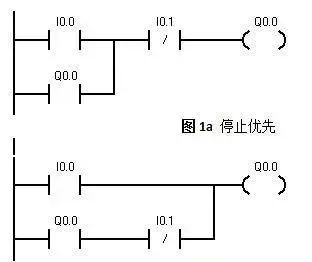
Figure 1 Start Priority
2. Interlock Control Circuit
In the interlock circuit shown in Figure 2, I0.0 and I0.1 are the start buttons, and I0.2 is the stop button.
In Figure 2(a), Q0.0 and Q0.1 are interlocked via outputs; one must be powered before the other can start, meaning it must stop before starting the other.
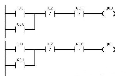 Figure 2 (a)
In Figure 2(b), the start and output are doubly interlocked.
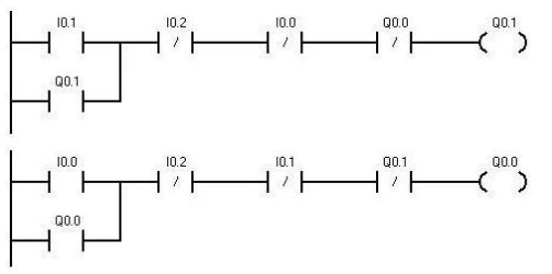
Figure 2 (b)
3. Multi-Location Control Circuit
The ladder diagram shown in Figure 3 is a multi-location control circuit. I0.0, I0.1, and I0.2 are the multi-location start buttons, and I0.3, I0.4, and I0.5 are the multi-location stop buttons.
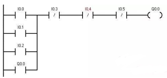 Figure 3
4. Sequential Control Circuit
For example, there are 3 motors. Press the start button I0.0, and the three motors Q0.0, Q0.1, and Q0.2 start sequentially; press the stop button I0.1, and the three motors Q0.0, Q0.1, and Q0.2 stop sequentially in reverse order. This program is widely used in sequential control machines such as belt conveyors. The sequential control ladder diagram is shown in Figure 4.
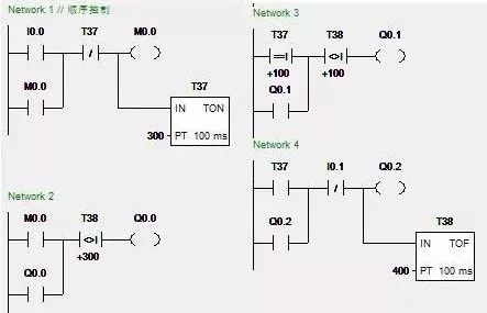
Figure 4
In the diagram, when starting, I0.0 is ON, using a powered delay timer relay T37 to start the motors sequentially through comparison instructions. When the current value of T37 equals 100, that is, after a delay of 10 seconds, Q0.1 starts, and after 20 seconds, Q0.2 starts. When stopping, I0.1 is ON, using a powered delay timer relay T38 to stop the motors sequentially in reverse order.
5. Frequency Division Circuit
The frequency division circuit is also called a single-button circuit. In many control scenarios, it is necessary to divide the control signal frequency; sometimes to save an input point, this circuit is also used.Figure 5 shows two ladder diagrams for implementing frequency division timing control.
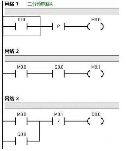 Figure 5 (a)
In Figure 5(a), when the first pulse arrives at 10.0, the PC scans for the first time, MO.0 is ON, Q0.0 is ON; during the second scan, Q0.0 is self-locking; when the second pulse arrives at 10.0, the PC scans for the first time, MO.0 is ON, MO.1 is ON, Q0.0 disconnects, during the second scan, MO.0 disconnects, Q0.0 remains disconnected; and so on.
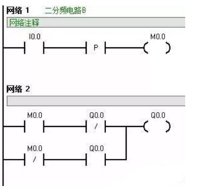 Figure 5 (b)
The principle of Figure 5(b) is similar to the previous ladder diagram and will not be explained further.
This circuit is often used to control a light in two states with one button. Multiple input buttons can be connected in parallel below I0.0 to achieve multiple switches controlling one light.
6. Flashing Circuit
The flashing circuit is also known as an oscillation circuit. The flashing circuit is essentially a clock circuit, which can have equal or unequal intervals of ON and OFF.
In actual program design, if the flashing function is used in the circuit, it is often directly implemented with two timers or one timer to form a flashing circuit.
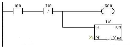
Figure 6(a)
Figure 6(a) is a simple flashing circuit control ladder diagram, suitable for situations where control accuracy is not high. Figures 6(b) and (c) are two commonly used flashing circuit control ladder diagrams.

Figure 6(b)
This circuit works regardless of other signals; when I0.0 is powered, it starts working, and the ON and OFF timing values can be set arbitrarily as needed. Figure 6(b) is a flashing circuit control ladder diagram with ON for 2 seconds and OFF for 1 second.
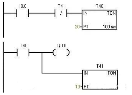
Figure 6(c)
Figure 6(c) is a flashing circuit control ladder diagram with OFF for 2 seconds and ON for 1 second.
Familiarity with the above control diagrams will greatly enhance the usage of timers.