This section discussesserial communication and the basic theories of communication.
1. Preliminary Knowledge of Serial Ports
1. Classification of Serial Ports
A serial port is a widely usedcommunication interface, characterized bylow cost, ease of use, and simple communication lines, allowingtwo devices to communicate with each other.
Note: Only two devices can be connected.
The microcontroller’s serial port enables communication between microcontrollers, between a microcontroller and a computer, and between a microcontroller and various modules, greatly expanding the application range of microcontrollers and enhancing the hardware capabilities of microcontroller systems.
The 51 microcontroller comes with a built-inUART (Universal Asynchronous Receiver Transmitter), which enables serial communication for the microcontroller.
1. USB to Serial is used for computer-MCU communication, and the serial assistant tool of stc-isp can be used on the computer to achieve communication between both parties.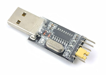
2. Gyroscope is used to detect theacceleration and attitude angles of the MCU.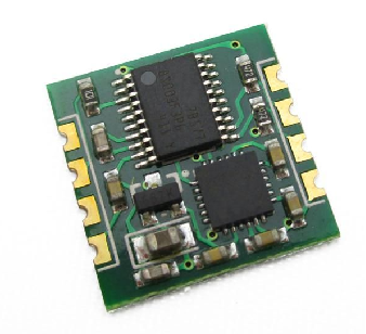
3. Bluetooth Interface enables Bluetooth connections, such as communication between mobile phones, computers, and microcontrollers.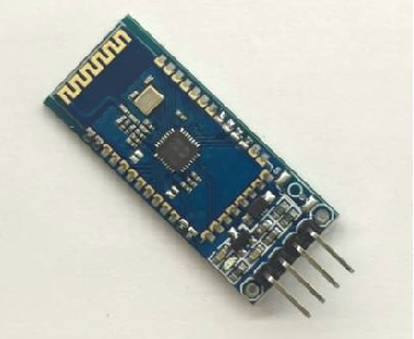
4. Desktop Serial Port 1 transmits data in 9 frames.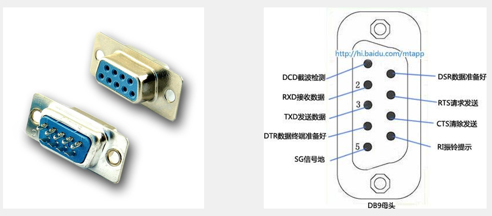
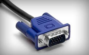
5. Desktop Serial Port 2 – VGA transmits video in 15 frames.
2. Serial Connection Methods
Simple bidirectional serial communication requirestwo communication lines (transmit lineTXD and receive lineRXD). TXD and RXD must becross-connected. For unidirectional data transmission, a single communication line can be used directly. When the voltage levels are inconsistent, a level conversion chip is needed.
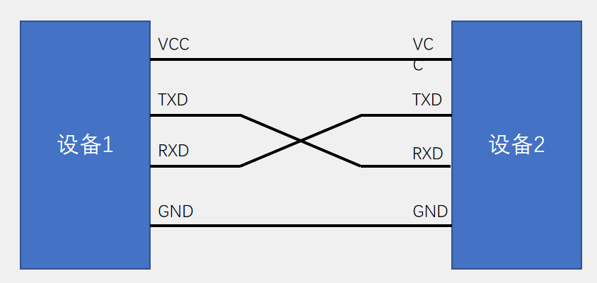
Small Knowledge TXD stands for transmit exchange data, and RXD stands for received exchange data, meaningtransmit data end and receive data end.
3. Voltage Level Standards
The voltage level standard isthe representation of data 1 and data 0, which isthe correspondence between the specified voltage in the transmission cable and the data. The commonly used voltage standards for serial ports are as follows:
TTL Level: +5V represents 1, 0V represents 0; commonly usedRS232 Level: -3~-15V represents 1, +3~+15V represents 0;RS485 Level: differential voltage of +2~+6V represents 1, -2~-6V represents 0 (differential signal).
Comparison of TTL, RS232, and RS485 voltage standards and their usage scenarios:
| Voltage Type | Voltage Representation | Typical Characteristics | Common Scenarios |
|---|---|---|---|
| TTL Level | +5V represents 1, 0V represents 0 | Low power consumption, low cost, suitable forshort distances, commonly used for internal communication within chips. | Communication between internal chips and peripherals on microcontroller development boards (e.g., LED, button interfaces), internal transmission of sensor data collection modules in low-speed embedded systems. |
| RS232 Level | -3 ~ -15V represents 1, +3 ~ +15V represents 0 | Uses single-ended signal transmission, large voltage amplitude, has certain anti-interference capability,short communication distance | Serial communication between early computers and external devices (e.g., mouse, modem), such as the COM port (serial port) connection of computers. |
| RS485 Level | Two-wire voltage difference +2 ~ +6V represents 1, -2 ~ -6V represents 0 (differential signal) | Uses differential signal transmission, strong anti-interference capability,long communication distance (up to about 1200 meters) | Distributed systems in industrial control (communication between sensor nodes, actuators, controllers), intelligent building monitoring systems (connecting access control, elevators, environmental monitoring devices), power monitoring, traffic monitoring, etc. |
2. Comparison of Communication Interfaces
The above explanations cover all knowledge about serial ports; below we will look at communication methods from the perspective of the entire electronics industry.
 Other communication methods include: CAN, USB, etc.
Below are their characteristics and usage scenarios:
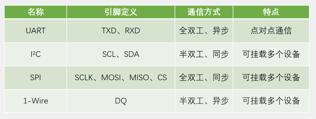
UART (Universal Asynchronous Receiver Transmitter)
- Characteristics: Full-duplex asynchronous communication, independent transmission and reception, no need for a synchronized clock, both parties must have the same baud rate; point-to-point communication, simple and easy to use.
- Common Scenarios: Communication between microcontrollers and computer serial debugging assistants,data exchange between embedded devices and simple peripherals (such asBluetooth modules, GPS modules).
I²C (Inter-Integrated Circuit)
- Characteristics: Half-duplex synchronous communication, data is transmitted through one clock line (SCL) and one data line (SDA); supports multiple device connections, devices are distinguished by addresses; has an acknowledgment mechanism to ensure data transmission reliability.
- Common Scenarios: Communication between chips on the motherboard, such as data transmission between EEPROM storage chips, sensors (e.g., temperature sensors, accelerometers) and the main control chip.
SPI (Serial Peripheral Interface)
- Characteristics: Full-duplex synchronous communication, multiple lines (clock line SCLK, master out slave in line MOSI, master in slave out line MISO, chip select line CS); fast transmission speed; can connect multiple slave devices, controlled individually through the CS line.
- Common Scenarios: High-speed data transmission scenarios, such as communication between Flash memory and the main control chip,data transmission between LCD displays and controllers.
1-Wire (Single Wire)
- Characteristics: Half-duplex asynchronous communication, requires only one data line (DQ) for data and power transmission; supports multiple device connections, identified by unique ROM codes.
- Common Scenarios: Scenarios with strict wiring requirements and fewer devices, such as networking digital temperature sensors (DS18B20), simple distributed I/O expansion.
USB (Universal Serial Bus)
- Characteristics:
- Control Transfer: Reliable bidirectional, used for device configuration, status detection, and command transmission, small data volume, high priority.
- Isochronous Transfer: Used for time-sensitive continuous communication, guarantees bandwidth and intervals, high real-time performance, large data volume, allows for some errors.
- Interrupt Transfer: Unidirectional (bidirectional requires two endpoints), timed polling, suitable for a small amount of non-continuous data that needs to be transmitted promptly.
- Bulk Transfer: Reliable unidirectional, utilizes bus idle bandwidth, suitable for large amounts of data that are not time-sensitive.
- Standardized interface, good expandability, ports can be expanded through USB hubs.
- Supports plug-and-play and hot-swapping.
- Flexible power supply, devices can be powered via USB or other means.
- Various transmission rates, such as USB 2.0 high speed at 480Mbps, full speed at 12Mbps, low speed at 1.5Mbps, and USB 3.0 and higher versions at even faster rates.
- Four communication modes:
CAN (Controller Area Network)
- Characteristics:
- Multi-master control, all units can send messages when the bus is idle, higher priority units send first.
- Uses differential signal transmission, strong anti-interference capability.
- Broadcast communication, all nodes can receive data, specific nodes respond.
- Has conflict detection and handling mechanisms, good real-time performance.
- Data is transmitted in frames, including identifiers, data fields, checksum fields, etc.
- Nodes can actively send data at any time.
- Has error detection, notification, and handling mechanisms, can isolate faulty units.
- Common Scenarios:Communication within automotive electronic systems, such as engine control, body control, in-car entertainment systems; industrial automation control fields, such as distributed control systems,robot control; equipment monitoring systems in smart buildings.
3. Communication-Related Terminology
| Term | Explanation |
|---|---|
| Full Duplex | Both parties in communication can transmit data to each other at the same time, both can send and receive simultaneously. For example, during aphone call, both parties can talk and hear each other at the same time. |
| Half Duplex | Both parties can transmit data to each other, but musttime-share a single data line, cannot send and receive simultaneously. Like a walkie-talkie, one party can speak while the other can only receive, and cannot respond at the same time. |
| Simplex | Communication can onlysend in one direction, no reverse transmission. For example, aremote control can only control the device, but the device cannot control the remote control. |
| Asynchronous | Both parties agree on the communication rate independently,without relying on a common clock signal. In serial communication (such as UART), both parties transmit data at their set baud rates. |
| Synchronous | Both parties rely on a clock line to agree on the communication rate, data transmission is synchronized with the clock signal. Like SPI and I²C communication, the clock line coordinates the rhythm of data transmission and reception. |
| Bus | The data transmission line connecting various devices, like a road connecting households, enabling data exchange between devices. For example, the system bus inside a computer connects the CPU, memory, hard drives, etc. |
4. Serial Protocol of the 51 Microcontroller
1. Serial Port Module on the Microcontroller
1. Location
The location is shown in the figure, P3.0 and P3.1 are multiplexed for serial transmission and reception: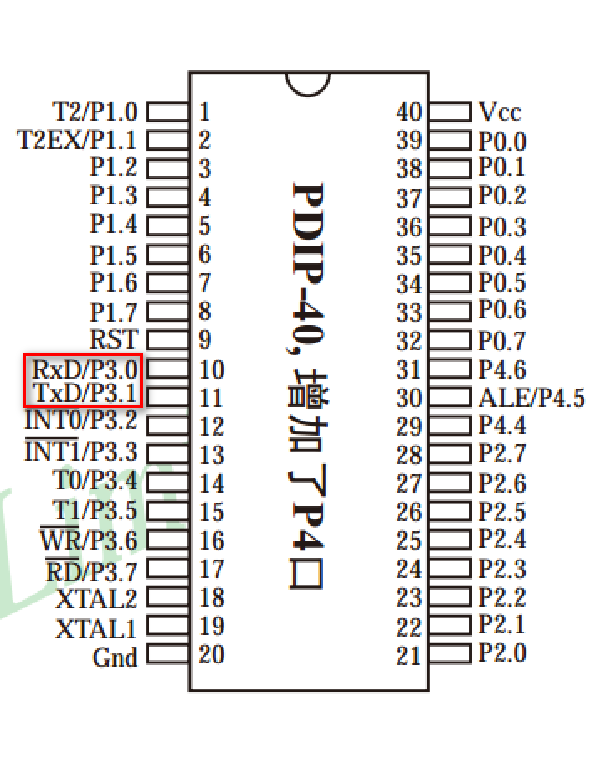
2. UART
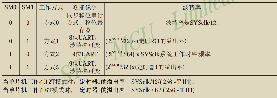
The STC89C52 has1 UART. The UART of the STC89C52 hasfour working modes:
| Working Mode | Mode Name | Mode Characteristics |
|---|---|---|
| Mode 0 | Synchronous Shift Register | For synchronous working mode, used as a shift register |
| Mode 1 | 8-bit UART | Asynchronous communication mode for 8-bit data, variable baud rate, is the more commonly used working mode |
| Mode 2 | 9-bit UART | Asynchronous communication mode for 9-bit data, fixed baud rate |
| Mode 3 | 9-bit UART | Also an asynchronous communication mode for 9-bit data, variable baud rate |
We willonly explain Mode 1.
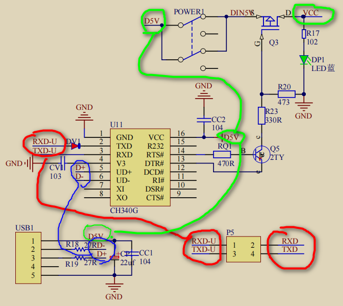
3. Circuit Diagram of the Microcontroller
2. Serial Port Parameters
1. Baud Rate: The rate of serial communication(the number of symbols (code elements) transmitted per second (can be bits) (the interval time for sending and receiving each data bit)
During serial communication, it isasynchronous, without clock constraints, so a communication rate must be agreed upon,when to sample, this is the baud rate.
2. Parity Bit: Used for data verification
3. Stop Bit: Used for data frame intervals
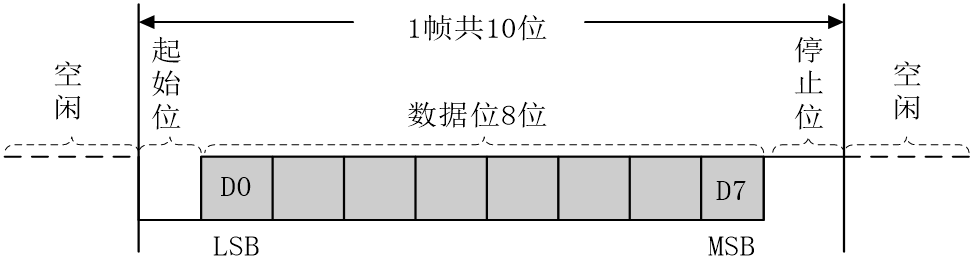
8-bit Data Format
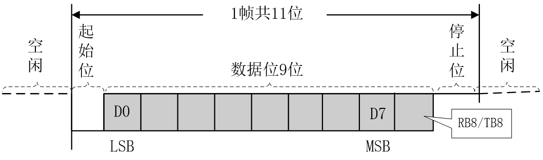
9-bit Data Format
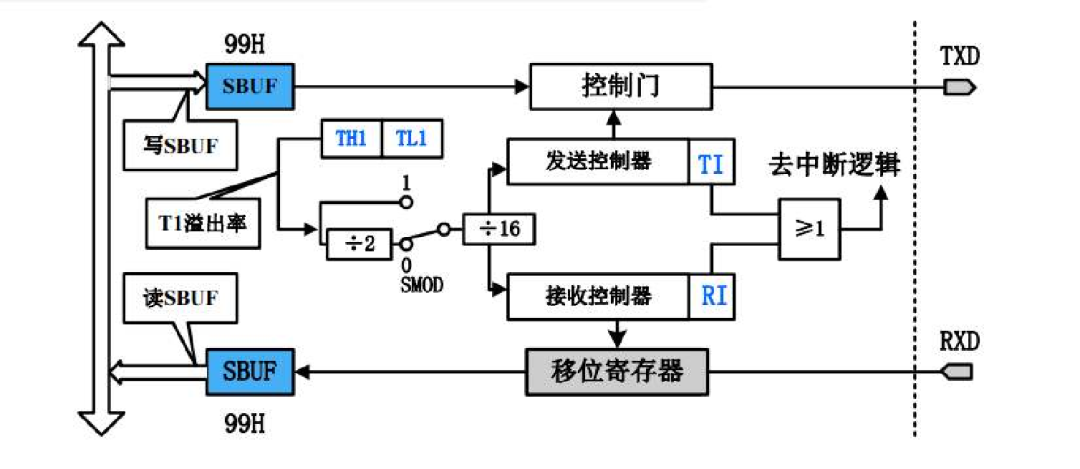
3. Serial Port Mode Diagram
Serial Port Architecture Diagram
 Annotated
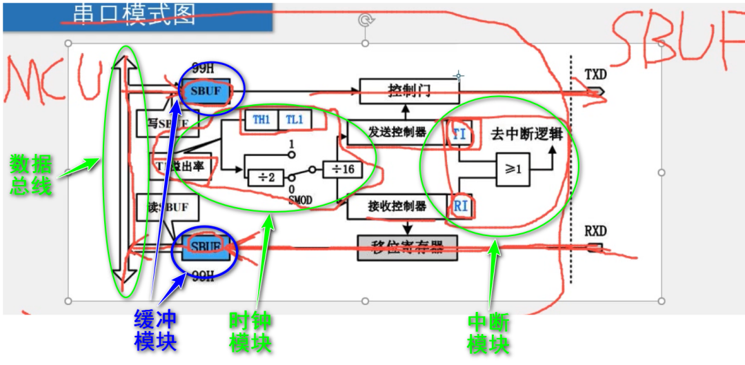
SBUF
The serial data buffer register is physicallytwo independent registers, but occupies the same address. During write operations, the data is written to the transmit register, and during read operations, the data is read from the receive register (this is actuallythe high-speed buffer of Linux, where data read and write will first go here)
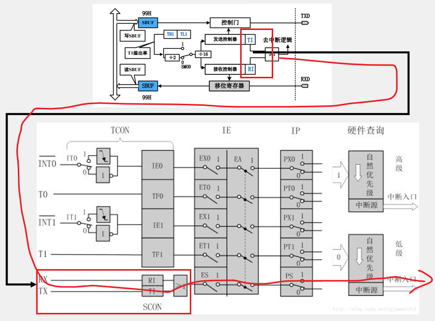
Interaction between Serial Port and Interrupt System
4. Serial-Related Registers
Registers ==> Switches for configuring serial port modes!
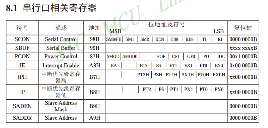
SCON Serial Control Register
PCON Power Control Register
5. Baud Rate Calculation Method
1. Serial Port Usage Process
Initialize registers -> MCU enters interrupt when receiving -> Call when MCU sends.
2. Baud Rate Generation Mechanism
The 51 microcontroller uses the overflow rate of Timer T1 as the measure of baud rate.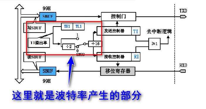 For example: Now the crystal oscillator frequency is 12MHz, generating abaud rate of 4800, with an error of0.16%, how is the baud rate and error obtained? As shown in the figure:
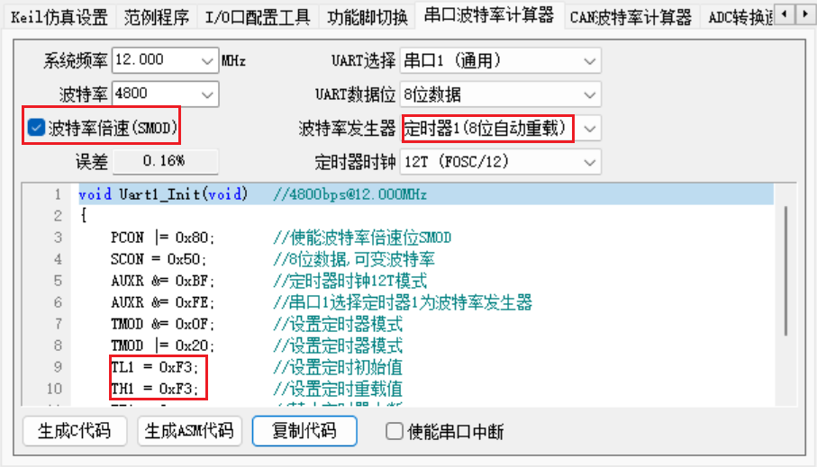
The timer is set to8-bit auto-reload, so the overflow is 256. The generated code is as follows:
void Uart1_Init(void) //[email protected]
{
 PCON |= 0x80;  //Enable baud rate double speed bit SMOD
 SCON = 0x50;  //8-bit data, variable baud rate
 AUXR &= 0xBF;  //Timer clock 12T mode
 AUXR &= 0xFE;  //Select Timer 1 as baud rate generator for serial port 1
 TMOD &= 0x0F;  //Set timer mode
 TMOD |= 0x20;  //Set timer mode
 TL1 = 0xF3;   //Set timer initial value
 TH1 = 0xF3;   //Set timer reload value
 ET1 = 0;   //Disable timer interrupt
 TR1 = 1;   //Start Timer 1
}
As can be seen, TL1=0xF3, TH1=0xF3, since it is checked, the total initial value of Timer T1 is: TL1=0xFC=243. The difference between the overflow value of 256 is: Δ=13. Since under 12 division, each vibration is 1us, the overflow time is 13us. Therefore, the overflow rate is: 1/13MHz. The figure shows that SMOD is checked to double the baud rate, so baud rate=2^1/32*(1/13*10^6)=1000000/16/13=4,807.69bps
The baud rate calculated here is: 4800bps, so an additional 7.69bps is present, making the error rate: 7.69/4800=0.0016=0.16%, this is theerror rate!
This is the baud rate calculation formula; for specifics, please refer to the 8052 user manual.
5. Practical Application
1. Microcontroller -> Computer Sending Data
Serial Port Initialization
void Uart1_Init(void) //[email protected]
{
 PCON |= 0x80;  //Enable baud rate double speed bit SMOD
 SCON = 0x50;  //8-bit data, variable baud rate
 TMOD &= 0x0F;  //Set timer mode
 TMOD |= 0x20;  //Set timer mode
 TL1 = 0xF4;   //Set timer initial value
 TH1 = 0xF4;   //Set timer reload value
 ET1 = 0;   //Disable timer interrupt
 TR1 = 1;   //Start Timer 1
 ES = 1;    //Enable serial port 1 interrupt
}
Send Function
void UART_SendByte(unsigned char Byte){
 SBUF=Byte;
 while(TI==0){//Wait for successful send

 }
 TI=0;//Reset successful send flag
}
Main Function
#include <REGX52.h>
#include "lcd1602.h"
#include "uart.h"
void main()
{
    unsigned char Sec = 0;
    Uart1_Init();
    lcd1602_init();
    while (1)
    {
        char str[2];
        UART_SendByte(Sec++);
        str[0] = Sec + '0';
        str[1] = '\0';
        lcd1602_show_string(0, 0, str);//Display sent data on LCD
        delay_ms(1000);
    }
}
Implementation Effect:
Image:
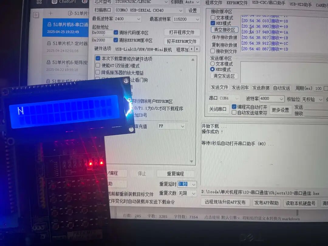
It can be seen that the data received on the display screen and the computer is consistent.
Video:
1. Computer -> Microcontroller Sending Data
Serial Port Initialization Function
void Uart1_Init(void) //[email protected]
{
 PCON |= 0x80;  //Enable baud rate double speed bit SMOD
 SCON = 0x50;  //8-bit data, variable baud rate
 TMOD &= 0x0F;  //Set timer mode
 TMOD |= 0x20;  //Set timer mode
 TL1 = 0xF4;   //Set timer initial value
 TH1 = 0xF4;   //Set timer reload value
 ET1 = 0;  //Disable timer 1 interrupt
 TR1 = 1;  //Start Timer 1
 EA=1;//Enable global interrupt
 ES=1;//Enable serial port interrupt (must be enabled, otherwise it won't work!)
}
Receive Interrupt Function
void UART_Routine() interrupt 4//Serial port receive data processing interrupt function from computer
{
 if (RI)    //Check serial port 1 receive interrupt
 {
  P2=~SBUF;    //Read data, invert and output to LED
  UART_SendByte(SBUF); //Send back the received data to the serial port
  RI = 0;   //Clear serial port 1 receive interrupt request flag
 }
}
Main Function
#include <REGX52.h>
#include "lcd1602.h"
#include "uart.h"
void MCU2Computer(){ //This is for MCU to send data to the computer, not used this time
 static unsigned char Sec;
 char str[2];
 UART_SendByte(Sec++);
 str[0] = Sec + '0';
 str[1] = '\0';
 lcd1602_show_string(0, 0, str);
 delay_ms(1000);
}
void main()
{
    Uart1_Init();//Serial port initialization
    lcd1602_init();
    while (1)
    {

    }
}
Experimental Effect
Image:
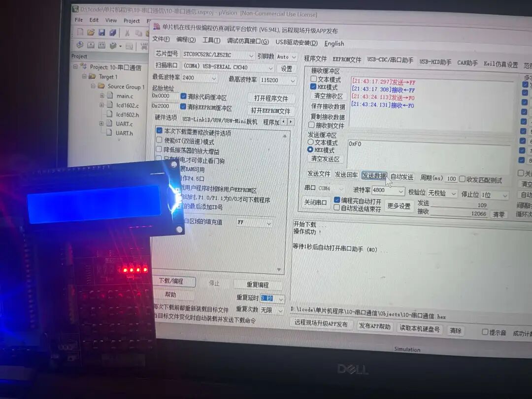 It can be seen that four LED lights are lit, which is consistent with expectations.
Video: