1. Operating Environment
- Simulation Software: Proteus 8.17 SP2
- Programming Software: KEIL C51 V961(All software and installation tutorials can be found in the Baidu Cloud link at the end of this article)
2. Project Overview
 This system is based on the AT89C51 microcontroller as the core control unit, meticulously designed as a traffic light simulation project. The system grants users the freedom to control the duration of the traffic lights through a convenient dip switch. It features two distinct operating modes: normal operation mode and night mode. During normal operation mode, the system accurately replicates the operational logic of everyday traffic signals, ensuring orderly traffic flow; while in night mode, the system employs a unique design where both directions flash yellow lights, aiming to provide clearer visual cues for vehicles, allowing drivers to quickly and safely navigate intersections after assessing road conditions, effectively enhancing nighttime traffic efficiency.
 The resource package includes simulation source files, program source files, and software installation package links along with installation tutorials links.
3. Hardware Description
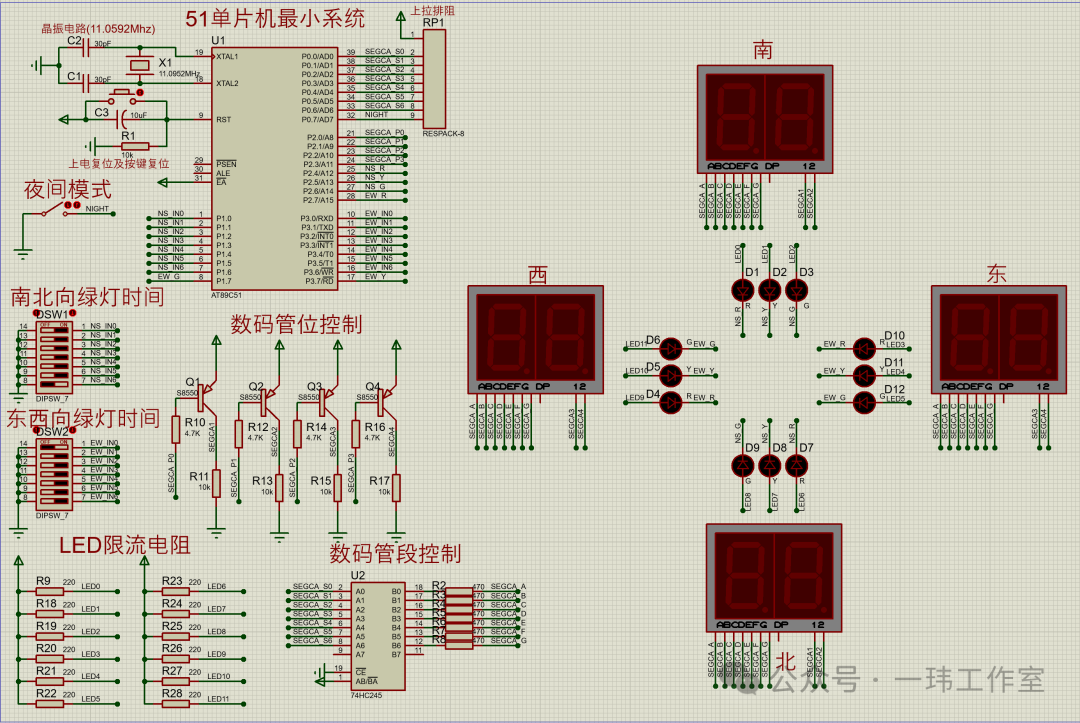
The hardware simulation circuit includes the minimum system of the microcontroller, the traffic light display system, and the dip switch input.
1. Minimum System of the Microcontroller
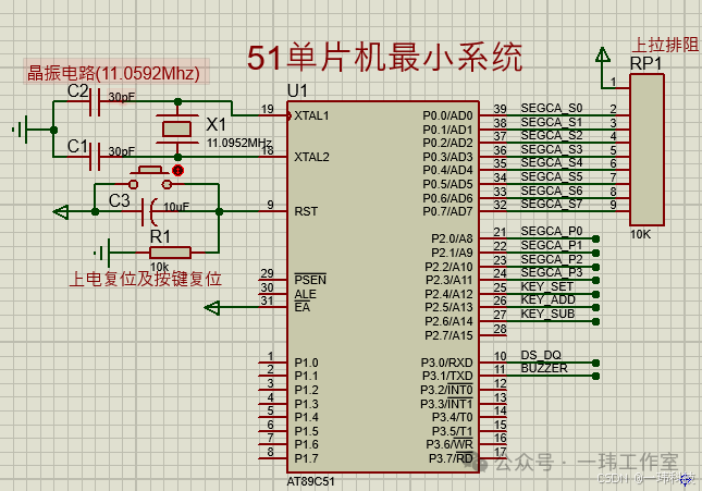 It mainly consists of the AT89C51 microcontroller and its peripheral circuits, which include the following parts: (1) Oscillator Circuit: Uses a frequency of 11.0592MHz to provide precise clock signals for the microcontroller; (2) Reset Circuit: Designed to include both power-on reset and manual button reset modes; (3) Pull-up Resistor on P0 Port: When using the P0 port of the 51 microcontroller as a general input/output port, an external pull-up resistor must be connected to ensure signal stability.
2. Traffic Light Display System
This system includes a digital tube display module and an LED display module.
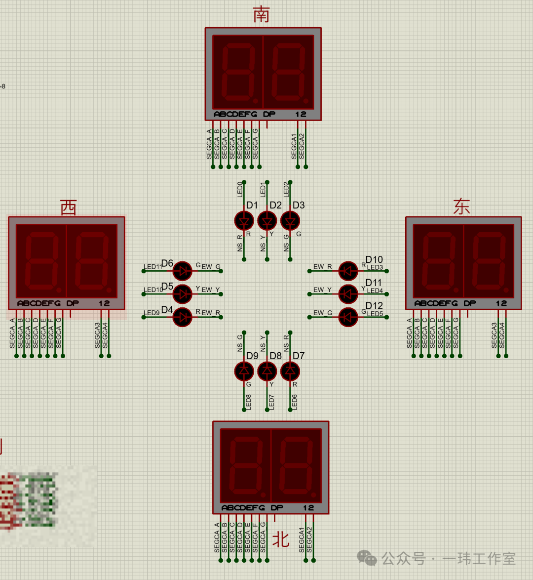
(1) Digital Tube Display Module
Each direction uses a two-digit common anode digital tube, where the north-south and east-west digital tubes share a common terminal, ensuring that the displayed numbers are synchronized.
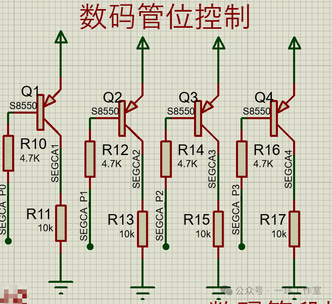 Thus, only four bits of control are needed to control all the digital tubes. The four bits are connected to the microcontroller’s P20-P23.
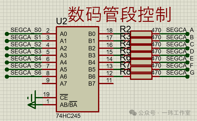 In terms of segment control for the digital tube, to prevent excessive current and inconsistent brightness, a 470-ohm resistor is connected in series with each segment to limit the current. Additionally, to prevent excessive current from flowing into the microcontroller, we use the 74HC245 chip to control the segments of the digital tube. The operation of the 74HC245 chip is managed by the P0 port of the microcontroller, ensuring the stability and safe operation of the entire digital tube segment control circuit, avoiding potential circuit failures or performance degradation due to excessive current.
(2) Traffic Light LED Display Module
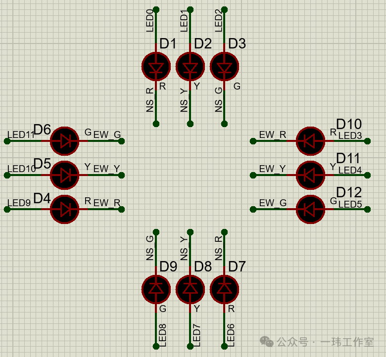 The traffic light LED display module is set up with four groups, each corresponding to a direction’s red, yellow, and green lights, totaling 12 LED lights. The north-south and east-west LED lights share a common terminal, ensuring synchronized color display. Thus, only 6 IO ports are needed to control all the LED lights, connected to P24-P27, P37, and P17.
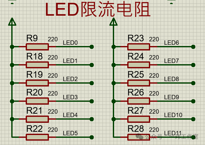
A total of 12 LED lights, with each line connected in series with a 220-ohm resistor to limit the current.
(3) Green Light Time Setting Circuit
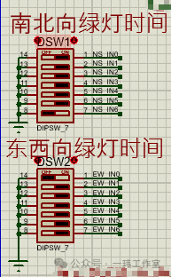
The green light time for both east-west and north-south directions uses a 6-bit dip switch as binary input to the microcontroller, allowing a setting range of 15s-90s.
(4) Night Mode Control Circuit
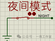 A switch is used to control the activation and deactivation of night mode. It connects to the microcontroller’s P27 port. When the switch is open, it operates in normal traffic light mode; when closed, it enters night mode. In night mode, both the north-south and east-west LED lights flash yellow, while the digital tube is turned off.
4. Software Description
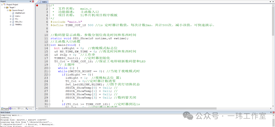
The program for this project is written in C language, compiled without warnings or errors. The program design adopts modular programming, with each functional module operating independently, facilitating program modification and maintenance; it also includes extensive comments, making the program’s functionality and implementation process easier to understand. The project program includes a main module, IO port module, digital tube module, and timer module, totaling four modules.
- Main Function Module: Coordinates the control of each module to implement the working logic of the traffic light. Due to the long working time of the traffic light, a complete demonstration takes a long time; therefore, a count value with a 1s time base is defined before the main function, and reducing this value allows for a quick demonstration.
- IO Port Module: This module provides functions related to IO port operations, such as reading green light time setting inputs, setting LED light states, etc.
- Digital Tube Module: All operations related to the digital tube are defined in this module, providing a display buffer and refresh function. Users only need to write the content to be displayed in the display buffer and call the refresh function in the timer interrupt to achieve the display of the digital tube.
- Timer Module: This module provides a 2ms time base for the system and calls the digital tube display refresh function in the timer interrupt.
5. Project Access
Baidu Cloud link:
https://pan.baidu.com/s/17fxxA3bWEfHxj5JlgvBixQ?pwd=yiwe
Extraction Code: YIWE