When it comes to communication, many people find it difficult and feel lost. I had the same feeling when I first encountered communication concepts. I gathered a lot of materials, mostly theoretical, and it always felt like I had no starting point. After finally understanding it, I realized that the main reason for not grasping it was not that it was difficult, but rather that it is too complex. It is impossible to fully comprehend and digest everything at once. Only by breaking down this complex knowledge step by step and understanding it progressively can we ultimately master it.
In the previous article, I introduced the basic principles of communication (what is communication) and what RS485 is, helping everyone establish a basic concept of RS485 communication. In this article, we will start with the simplest step in communication, which is data transmission (sending data from PLC to a computer).
1. Experimental Tools
First, I want to tell you about the tools we will use in this article.
1. One S7-200 CPU (model doesn’t matter, preferably with two communication ports)
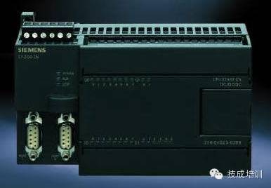
Figure 1-1
2. Serial Port Debugging Software
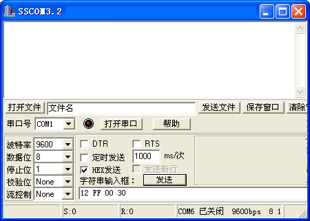
Figure 1-2
3. One USB to RS485 converter (RS232 to RS485 converter is also acceptable)
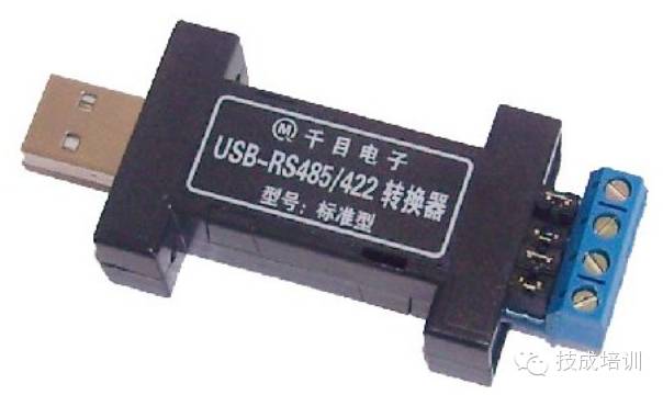
Figure 1-3
4. One 9-pin male connector
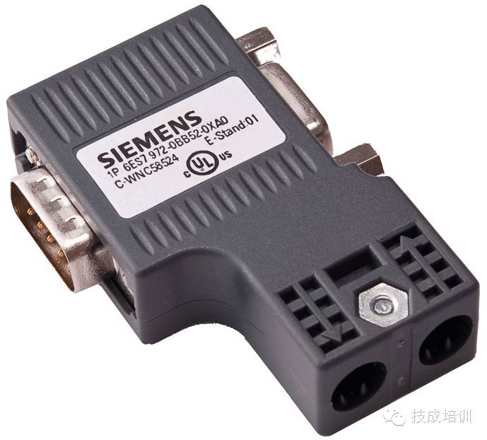
Figure 1-4
5. Two-core cable
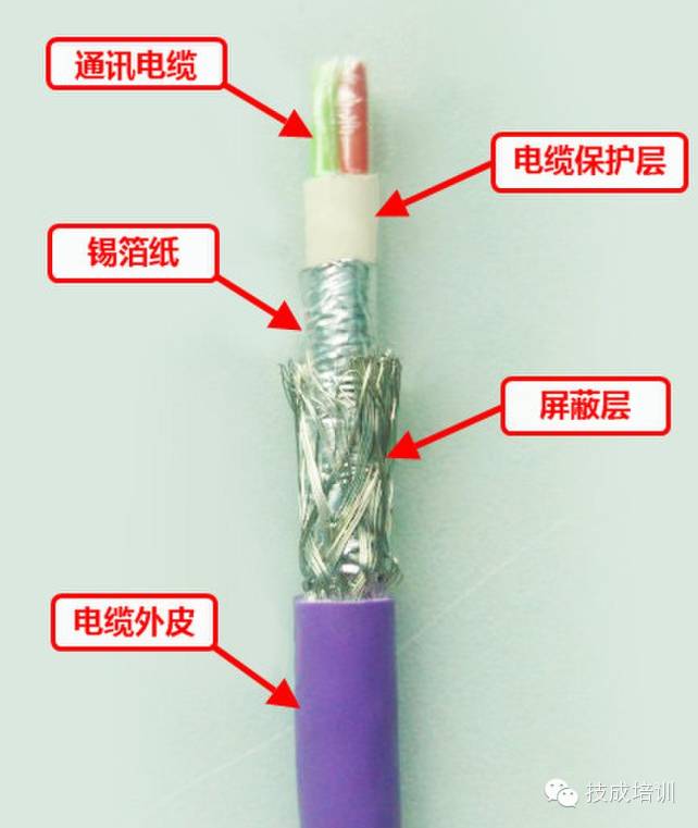
Figure 1-5
2. Experimental Procedure
Experiment Objective: To send one byte of data from PLC to the computer.
Experiment Operation: Use the S7-200 PLC to send one byte of data to the computer, which will be received via serial port debugging software. Since most computers today do not have RS485 communication ports, we need to use a USB to RS485 converter to ensure the computer can receive data from the PLC. Additionally, pay attention to the wiring: connect pin 3 of the 9-pin connector to the signal “+” on the USB to RS485 converter and pin 8 to the signal “-”.
3. Free Port Mode
When it comes to programming, everyone must first understand the free port mode of the S7-200. The default communication method of S7-200 is PPI communication, which does not allow for free data transmission. To transmit data freely, the communication interface of the S7-200 must be set to free port mode. The special bit registers SMB30 and SMB130 control the free port of the S7-200. SMB30 controls communication port 0 while SMB130 controls communication port 1. Of course, if there is only one communication port, only the special bit register SMB30 can be used. Let’s take a look at the meaning of these 8 bits as shown in Figure 3-1.
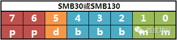
Figure 3-1
1) Bits 0 and 1: Protocol Selection
mm:
00 = Point-to-point interface protocol (PPI/slave mode)
01 = Free port protocol
10 = PPI/master mode
11 = Reserved (default is PPI/slave mode)
2) Bits 2, 3, and 4: Free Port Baud Rate Settings
bbb: 000 = 38400bps
001 = 19200bps
010 = 9600bps
011 = 4800bps
100 = 2400bps
101 = 1200bps
110 = 115200bps
111 = 57600bps
3) Bit 5: Data Bits per Character
d:
0 = 8 bits/character
1 = 7 bits/character
4) Bits 6 and 7: Parity Selection
pp:
00 = No parity
01 = Even parity
10 = No parity
11 = Odd parity
Additionally, I would like to add a concept. In the communication process, the smallest unit for sending and receiving is a character, not a bit. One character usually includes one start bit indicating the beginning of the character, one stop bit indicating the end of the character, one parity bit for verifying the correctness of the character, and either 8 or 7 data bits for transmitting information. The parity bit can be optional, and the data bit is usually 8 bits, which is 1 byte. Therefore, if a character includes a parity bit, it usually consists of 11 bits; if it does not include a parity bit, it consists of 10 bits.
Based on the introduction to the free port mode above, if we use free port mode on communication port 0 of the S7-200 CPU, and the baud rate is 9600bps without a parity bit, we must configure the data in SMB30 to 00001001 as shown in Figure 3-2, which converts to hexadecimal as 16#9.
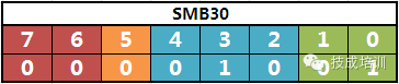
Figure 3-2
4. Program Writing
Before we start writing the program, we must first master the use of the S7-200 send instruction.
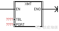
Figure 4-1
The XMT send instruction has two pins, TBL and PORT.
PORT: Communication port number; write 0 if using port 0, or write 1 if using port 1.
TBL: Defines the starting address and size of the send buffer. If TBL contains VB100 and VB100 holds 1, then the send buffer is VB101. When sending data, the data in VB101 will be sent. If VB100 holds 2, then the send buffer will be VB101 and VB102; when sending data, the data in VB101 and VB102 will be sent.
Now let’s look at the specific way to write the program.
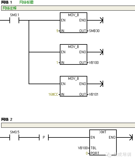
Figure 4-2
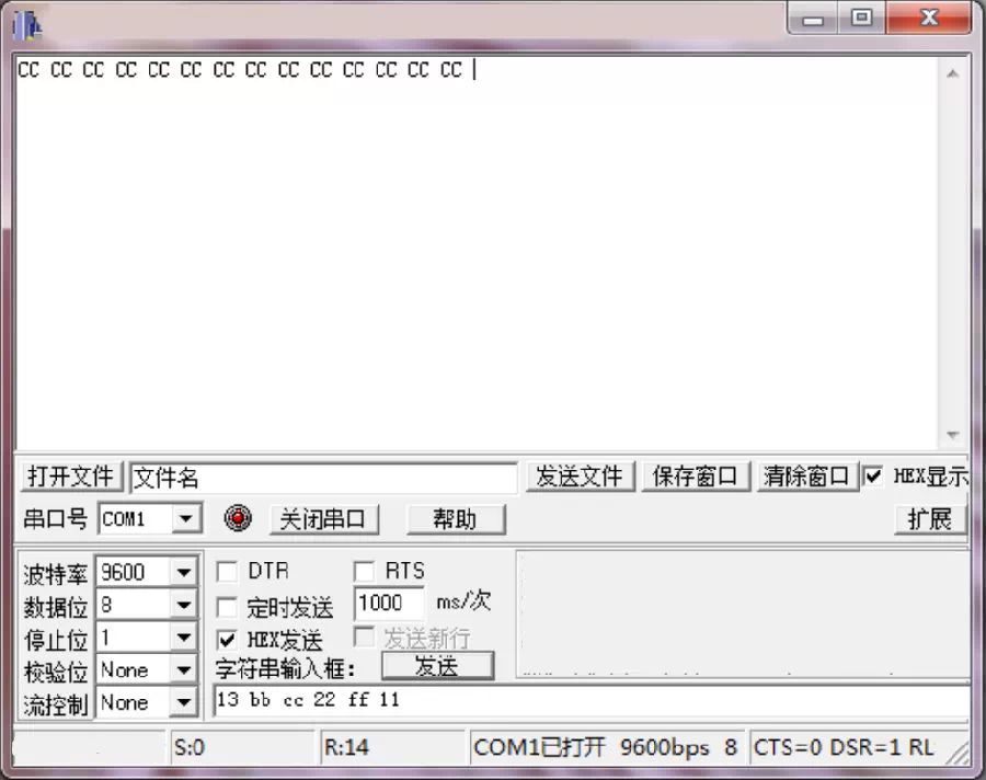
The program shown in Figure 4-2 is the simplest sending program. First, we define communication port 0 as a free port using SMB30, with a communication speed of 9600bps, and then define VB101 as the send buffer (because VB100 holds 1), sending the hexadecimal CC from VB101 to the computer at one-second intervals. Eventually, our computer will receive the character CC sent from the PLC at one-second intervals as shown in Figure 4-3.
Hurry up and share this with your friends!
Reply with the followingkeywords to get related articles
Mastering RS485 proximity switch multimeter electrician cable selection Free class PLCVideo previewFrequency converter control electrician mnemonic
Click “Read the Original” for more exciting content