
1. Characteristics of PLC Control System Ladder Diagrams
(1) Input Signals and Output Loads of the PLC Control System
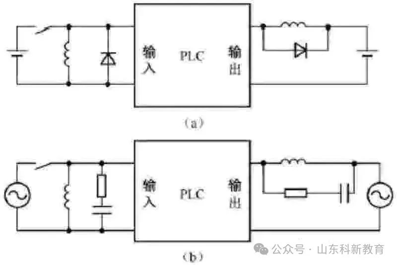
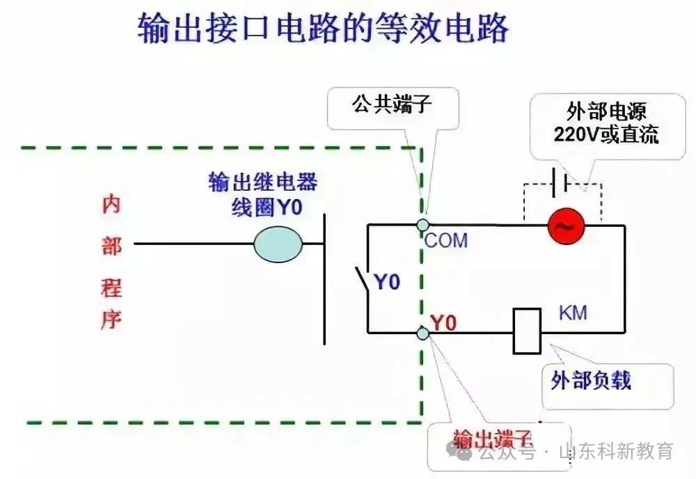
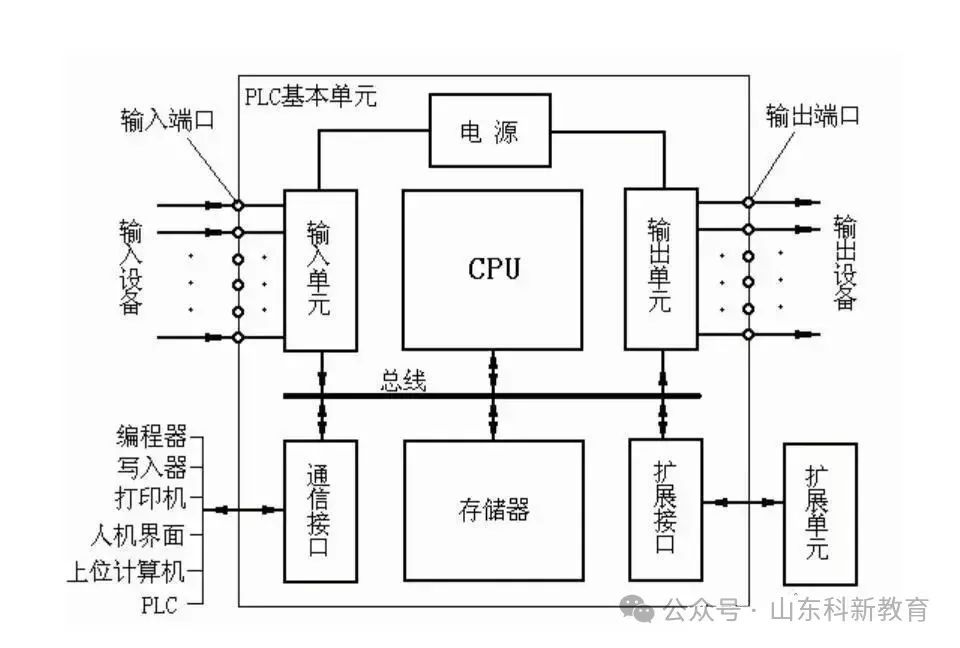
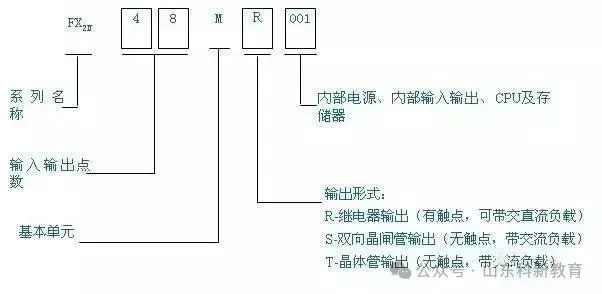
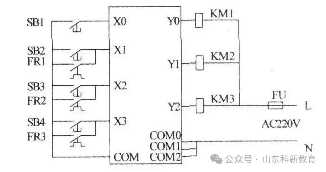
The actuators such as AC contactors and solenoid valves in the relay circuit diagram are controlled by the output relays of the PLC, with their coils connected to the output terminals of the PLC. Buttons, control switches, limit switches, proximity switches, etc., are used to provide control commands and feedback signals to the PLC, with their contacts connected to the input terminals of the PLC.
(2) Handling of Intermediate Relays and Time Relays in Relay Circuit Diagrams
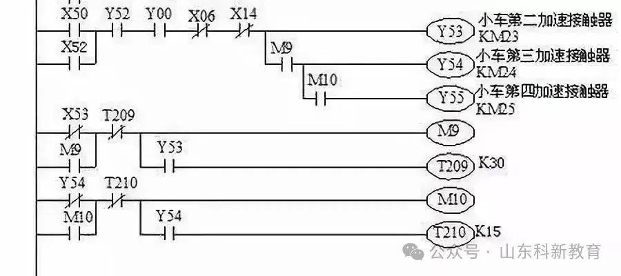
The functions of intermediate relays and time relays in the relay circuit diagram are accomplished using auxiliary relays and timers within the PLC, which are independent of the input and output relays of the PLC.
(3) Setting Intermediate Units
In the ladder diagram, if multiple coils are controlled by a certain contact in a series/parallel circuit, to simplify the circuit, an auxiliary relay controlled by that circuit can be set in the ladder diagram, which is similar to the intermediate relay in the relay circuit.
(4) Handling of Momentary Contacts of Time Relays
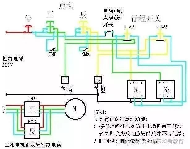
In addition to the delayed action contacts, time relays also have momentary contacts that act immediately when the coil is energized or de-energized. For time relays with momentary contacts, auxiliary relays can be connected in parallel at both ends of the timer coil in the ladder diagram, with the contacts of the latter corresponding to the momentary contacts of the time relay.
(5) Establishment of External Interlocking Circuits
To prevent the two contactors that control forward/reverse rotation from acting simultaneously, causing a three-phase power short circuit, in addition to setting up a soft interlocking circuit composed of normally open contacts in series with the coils of the corresponding output relays in the ladder diagram, a hard interlocking circuit should also be established externally to the PLC.
2. Structure Analysis of Ladder Diagrams
Whether to use general programming methods or sequential function chart programming methods; whether to use a sequential structure or a parallel sequence structure for the sequential function chart, and whether to program using start/stop circuits, stepping control instructions, or using set/reset instructions.
The decomposition of the ladder diagram starts with the operation of the main command circuit (e.g., buttons), tracing the line to the main circuit control devices (e.g., contactors) action, which involves many programming components and circuits, making it relatively difficult to trace.
No matter how complex the ladder diagram is, it is composed of some basic units. Based on the composition of the main circuit, using reverse tracing method, the ladder diagram and instruction statement table can be decomposed into several basic units corresponding to the electrical devices of the main circuit (e.g., motors), and then analyze step by step, finally using forward tracing method to connect the various links.
(1) Configuration and Function of Buttons, Limit Switches, and Selector Switches
In the PLC’s I/O wiring diagram, there are many limit switches and selector switches, as well as pressure relays, temperature relays, etc. These electrical components do not have attracting coils, and their contacts’ actions rely on external forces or other factors. Therefore, it is essential to first identify the external forces or factors that cause these contacts to act. Among them, limit switches are actuated or released by mechanical linkage mechanisms, while selector switches are generally operated manually, causing these limit switches and selector switches’ contacts to be in different working states during equipment operation, i.e., the closure and disconnection of contacts vary to meet different control requirements, which is a key point in the process of reading the diagram.
It is challenging to clarify the different working states of these limit switches and selector switches’ contacts solely by looking at the circuit diagram; it is necessary to combine the equipment manual and the detailed list of electrical components to clarify the purpose of the limit switches and selector switches, manipulate the mechanical linkage mechanisms of the limit switches, and understand the working states of the circuit under different closure or disconnection conditions.
(2) Using Reverse Tracing Method to Decompose Multi-Load (e.g., Multiple Motor Circuits) into Single Load (e.g., Single Motor) Circuits
According to the main contact symbols of the control devices in the main circuit, find the output relay controlling that load in the PLC’s I/O wiring diagram, then find the coil controlling that output relay in the ladder diagram and instruction statement table along with its relevant circuits, which constitutes the local circuit controlling that load.
In the ladder diagram and instruction statement table, it is easy to find the coil circuit of that output relay and its conditions for energization and de-energization, but finding the conditions that cause the energization and de-energization of that coil and its related circuits is not easy; the reverse tracing method can be used to search for:
The closure and disconnection of other programming component contacts in series or parallel with the output relay coil circuit are the conditions for the output relay to be energized or de-energized.
From these contacts, further find their coil circuits and related circuits, which may include other contactors and relay contacts…
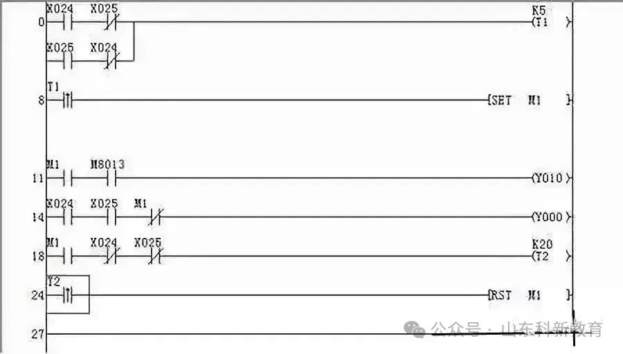
Continue searching until the input relay (main command device) is found. It is worth noting that when a programming component is energized or de-energized, all the operating states of the preceding and subsequent programming components driven by that programming component’s contacts should be identified without omission.
Identify the operating contacts of a programming component in other circuits; these contacts provide conditions for the energization and de-energization of other programming components or provide conditions for interlocking, causing other electrical components to act, driving the actuating devices.
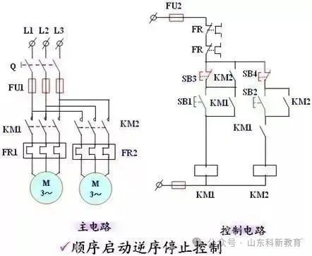
(3) Further Decompose the Single Load Circuit
The local circuit controlling a single load may still be complex and needs further decomposition until it is broken down into basic unit circuits.
(4) Notes on Decomposing Circuits
If the motor spindle is connected to a speed relay, the motor will form a stop braking circuit based on speed control principles.
If a rectifier is connected in the motor’s main circuit, it indicates that the motor uses an energy-consuming braking stop circuit.
(5) Collecting and Analyzing
Connect the basic unit circuits in series and analyze the entire circuit using forward tracing method.
Source: This article is reproduced from the internet, and the copyright belongs to the original author. If there are any copyright issues, please contact us in time for deletion. Thank you!

Scan to Follow
WeChat ID|13615417996
Follow the left QR code to get it for free
[Siemens Data Collection]