What is a PLC Sequential Function Chart?
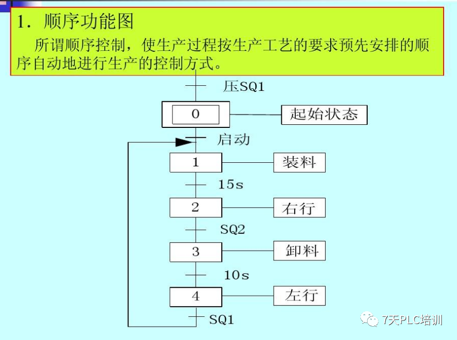
A sequential function chart is a graphical representation method that describes the process, functions, and characteristics of a sequential control system. It mainly consists of steps, directed segments, transitions (including transition conditions), and actions. Understanding and mastering each component is crucial for drawing a good sequential function chart.
Components of a Sequential Function Chart
1. Step
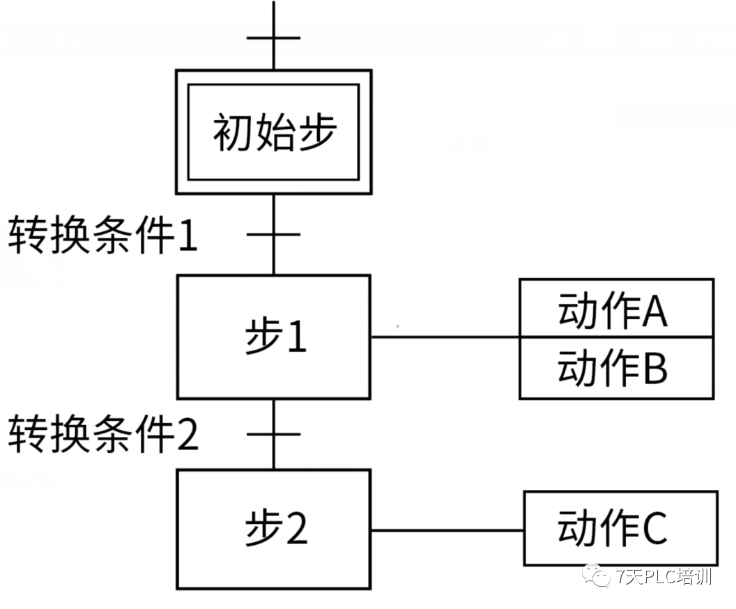
A step divides a working cycle in a sequential control system into several stages, and this stage is called a step. When the step is active, the corresponding action is executed; when the step is in a static state, the corresponding non-storage action is stopped.
2. Directed Segment
A directed segment connects steps together (with direction).
3. Transition
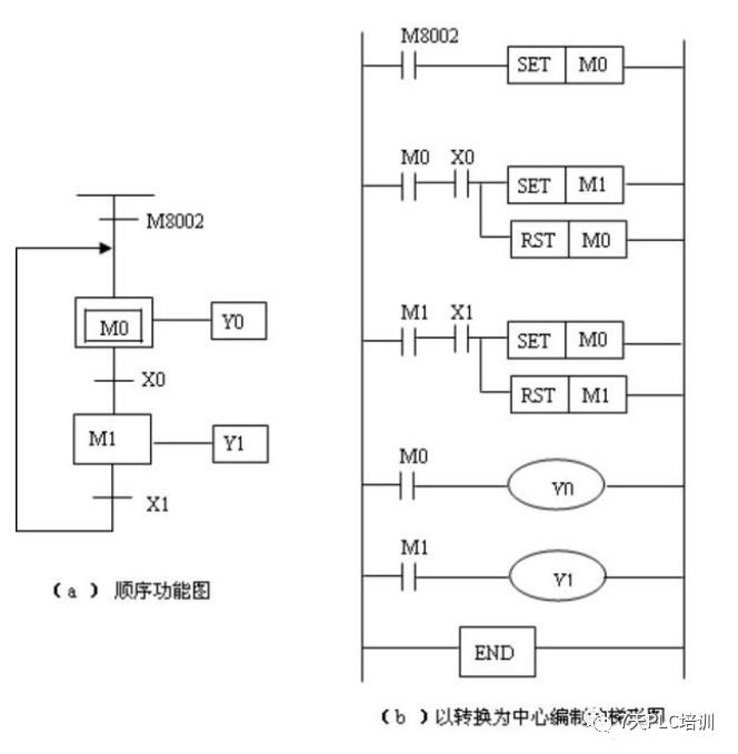
A transition is the switching condition when moving from one step to another, and the switching between two steps can be represented by a directed segment. The arrow of the directed segment representing the downward transition can be ignored.

The implementation of a transition must meet two conditions simultaneously:
1. All preceding steps of the transition must be active steps.
2. The corresponding transition conditions must be met.
4. Action
An action is the task to be performed by the step, which can be an output, timing, or counting.
 Notes
Notes
1. Two steps must not be directly connected; they must be separated by a transition.
2. Two transitions must not be directly connected; they must be separated by a step.
3. An initial step is essential; otherwise, the initial state cannot be represented, and the system cannot return to the stop state.
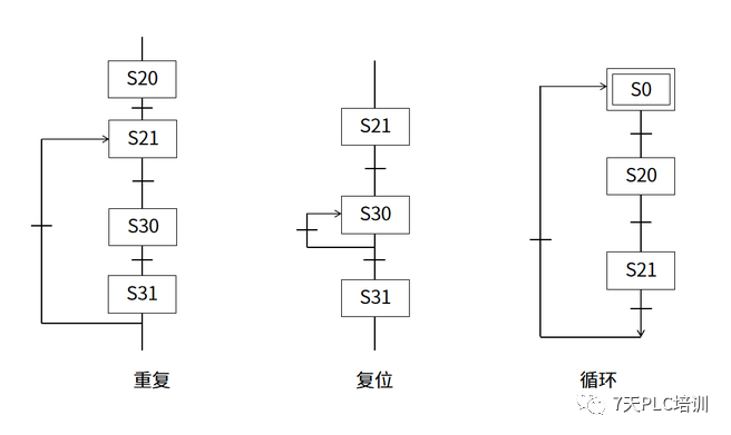
4. The automatic control system should be able to repeatedly execute the same process, forming a closed loop, meaning the last step returns to the initial step (single cycle) or the first step of the next cycle starts running (continuous loop).
5. Only when the current step is an active step can it change to an active step. Generally, programming components that do not have power-off holding function represent each step, and when entering RUN mode, they are all in a disconnected state, and the system cannot work. An initialization pulse N M8002 must be used as a transition condition to preset the initial step as the active step.

 Learn PLC together by scanning the QR code below