In a PLC control system, although the wiring work occupies a small proportion, it is the foundation of programming design. Only with correct wiring can programming proceed smoothly. To ensure the correctness of the wiring, a clear understanding of the input and output circuits inside the PLC is essential.
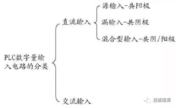
DC Input Circuit
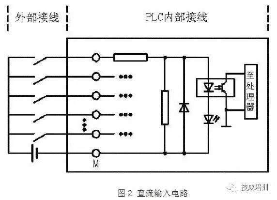
As shown in the figure above, this is one form of a DC input circuit (only one input circuit is drawn). When the external circuit switch is closed, the light-emitting diode in the internal optocoupler of the PLC lights up, and the phototransistor saturates and conducts. This conduction signal is then sent to the processor, allowing the CPU to recognize that there is a signal input on that line: when the external switch is open, the light-emitting diode in the optocoupler goes out, the phototransistor turns off, and the CPU recognizes that there is no signal on that line.
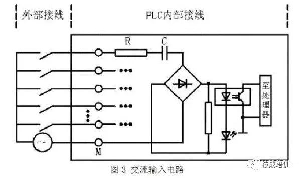
As shown in the figure above, we can see the difference between the AC input circuit and the DC input circuit: the main difference is the addition of a rectification stage. The input voltage for AC input is generally AC120V or 230V. The AC current passes through a resistor R for current limiting and a capacitor C for isolation, then is rectified to DC through a bridge rectifier, after which the working principle is the same as that of the DC input circuit.
From the above, it can be seen that due to the addition of current limiting, isolation, and rectification stages in the AC input circuit, the input signal’s delay time is longer than that of the DC input circuit, which is its disadvantage. However, since the input end is high voltage, the reliability of the input signal is higher than that of the DC input circuit.
Leakage Type Input Circuit
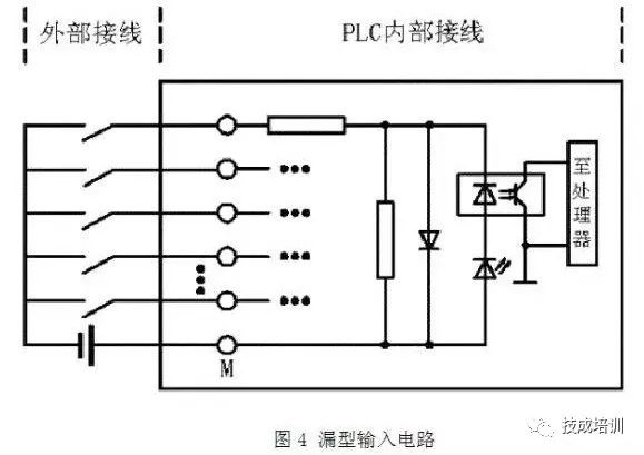
As shown in the figure above, the current flows from the PLC common terminal (COM terminal or M terminal) into the input, thus flowing out from the input terminal, which connects to the positive terminal of the external DC power supply.
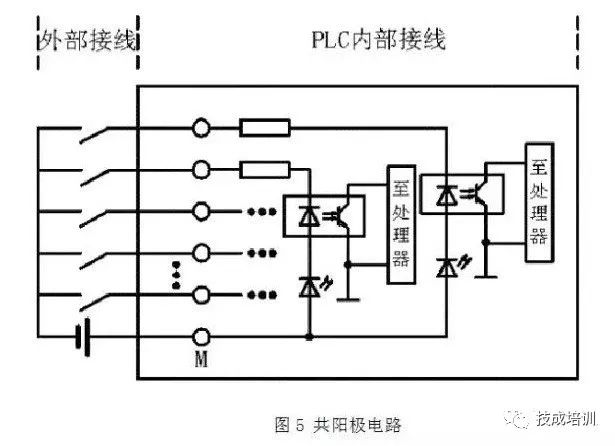
As shown in the figure above, this diagram only illustrates one input scenario. If there are multiple inputs, all the anodes of the input diodes are connected, forming a common anode circuit.
The Mitsubishi A series PLC input modules AX40/41/42/50/60 and Q series QX40/41/42 are all leakage type input modules.
The circuit shown in Figure 3 is also a form of source type input circuit, where the current direction is exactly opposite to that of the leakage type circuit. The source input circuit flows into the PLC’s input terminal and out from the common terminal, which connects to the negative terminal of the external power supply.
If all the cathodes of the input circuit diodes are connected, it forms a common cathode circuit, as shown in the figure below.
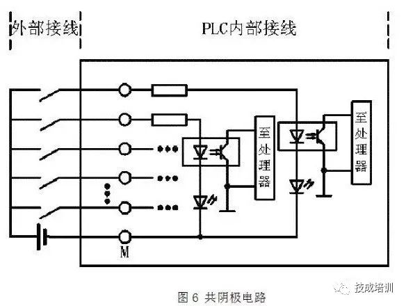
The Mitsubishi A series PLC input modules AX80/81/82 and Q series QX80/81 belong to this type of input circuit.
Mixed Type Input Circuit
Because this type of PLC common port can connect to either the positive or negative terminal of the external power supply, and has characteristics of both source input circuits and leakage input circuits, we can tentatively call this input circuit a mixed type input circuit, as shown in the figure below:
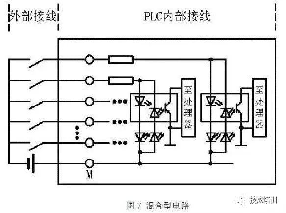
As a source input, the common terminal connects to the negative terminal of the power supply; as a leakage input, the common terminal connects to the positive terminal of the power supply. This allows for flexible wiring according to site needs.
The Mitsubishi A series PLC AX50-S1/60-S1/70/71/81-S1 and Q series QX70/71/72 belong to this category.
It should be noted that Mitsubishi and SIEMENS have opposite classifications for “source input” and “leakage input” circuits; the above is introduced according to Mitsubishi’s classification method.
Connecting External Switch Signals to PLC Input Circuits
The input signals external to the PLC, besides some dry contact signals like buttons, now some sensors also provide NPN and PNP open-collector output signals. The connection of dry contacts to the PLC input module is relatively simple. However, when it comes to different PLC input circuits, it can sometimes be confusing whether to use NPN input or PNP input.
The following will mainly introduce the connection of these two types of inputs to the PLC input circuits.As shown in the figure below, these are two forms of NPN and PNP output circuits.
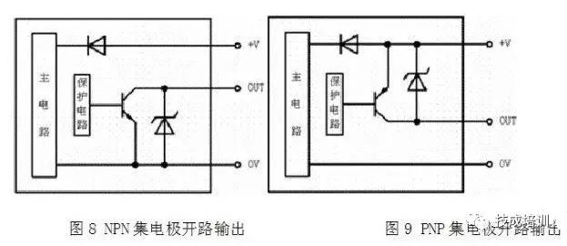
It can be seen that in the NPN open-collector output circuit, the output OUT terminal is connected to OV through a switching transistor. When the sensor operates, the switching transistor saturates and conducts, making the OUT terminal the same as OV, outputting a low-level signal; in the PNP open-collector output circuit, the output OUT terminal is connected to +V high-level signal through a switching transistor.
Connecting NPN and PNP Output Circuits to PLC Input Modules
From the above analysis, it can be seen that the NPN open-collector output is OV. When the OUT terminal is connected to the PLC input, the current flows out from the PLC’s input terminal and into the PLC’s common terminal, which is the form of the PLC’s leakage type circuit. Thus, NPN open-collector output can only connect to leakage type or mixed type input circuits of the PLC, as shown in the connection diagram below.
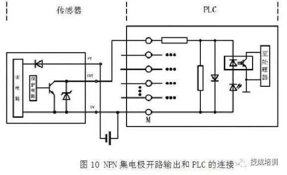
PNP Open-Collector Output
For +V high level, when the OUT terminal is connected to the PLC input, the current flows into the PLC’s input terminal and out from the PLC’s common terminal, which is the form of the PLC’s source type circuit. Thus, PNP open-collector output can only connect to source type or mixed type input circuits of the PLC, as shown in the connection diagram below.
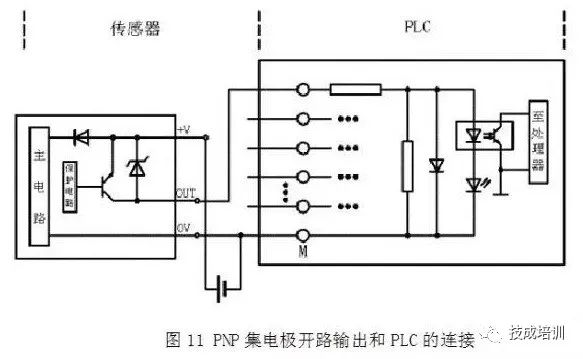
It is precisely because of the diversity of PLC input module circuit forms and external sensor output signals that we need to fully understand the types of PLC input circuits and the forms of sensor output signals before connecting the PLC input module. Only in this way can we ensure the correctness of the PLC input module wiring, preparing for subsequent PLC programming and debugging work.
Source: Internet

 Click here to like
 Free PLC and Electrical Courses, click to read the original text