1. Spacing Between SMDs
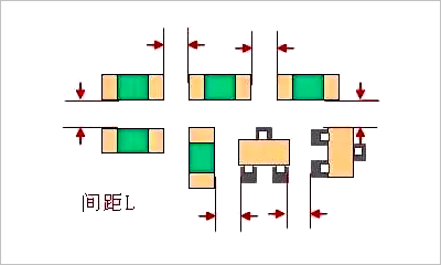
The spacing between SMDs should neither be too large (which wastes PCB area) nor too small to avoid solder paste printing adhesion and difficulties in soldering repairs.
The spacing can refer to the following specifications:
■ Same component: ≥ 0.3mm
■ Different components: ≥ 0.13×h+0.3mm (h is the maximum height difference between the nearby components)
■ For manual soldering and SMD, the distance requirement between components: ≥ 1.5mm.
2. Distance Between Through-Hole Components and SMDs
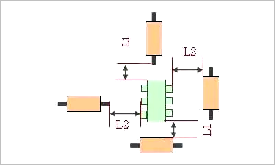 As shown in the figure, there should be sufficient distance between through-hole resistors and SMDs, recommended to be between 1-3mm. Due to the complexity of processing, the use of through-hole components is now rare. However, external sockets on the PCB are often through-hole.
3. Placement of Decoupling Capacitors for ICs
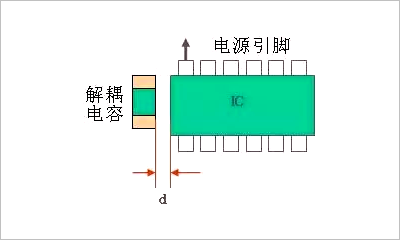
Decoupling capacitors should be placed near the power ports of each IC, as close to the IC’s power port as possible. If a chip has multiple power ports, decoupling capacitors should be laid out for each port.
4. Orientation and Distance of Components Near PCB Edge
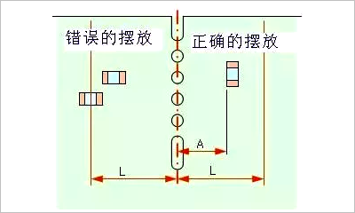
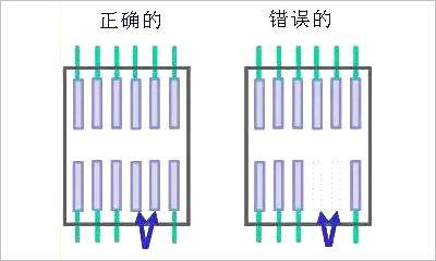
Since PCBs are usually made using panelization, components near the edge must meet two conditions.
The first is to be parallel to the cutting direction (to ensure uniform mechanical stress on the components, for example, if placed as shown on the left side of the figure, the stress direction on the two pads during panel separation may differ, potentially causing component detachment from the pads).
The second is that no components should be placed within a certain distance (to prevent damage to components during the PCB cutting process).
5. Adjacent Pads Connection
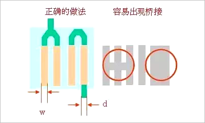 If adjacent pads need to be connected, first confirm the connections are made externally to avoid bridging, while also paying attention to the width of the copper traces.
6. Pads Falling in Pour Areas
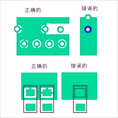
If pads fall within a pour area, the connection should be made as shown on the right, and the number of traces connected should be determined based on the current size.
If the left method is used, it will be difficult to solder or repair components, as the temperature disperses through the copper pour, making soldering difficult.
7. Pad Tear Drops
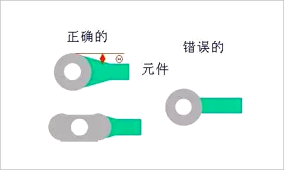
If the trace is smaller than the pad of a through-hole component, a tear drop should be added using the left method shown in the figure.
Adding a tear drop has several benefits:
(1) It prevents sudden width changes in signal traces that could cause reflections, allowing for a smoother transition between traces and component pads.
(2) It resolves the issue of connections between pads and traces being easily broken due to impact.
(3) It makes the PCB look more aesthetically pleasing.
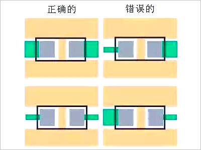
8. Consistent Width of Component Leads
9. Retain Unused Pin Pads
For example, in the case of a chip where two pins are not used, the physical pins still exist. If the right method is used, the two pins will be floating, which can easily cause interference.
If the chip pins are internally unconnected (NC), adding pads and grounding them can prevent interference.
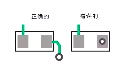
10. Avoid Holes on Pads
11. Distance Between Wires and PCB Edge
It is important that leads or components are not too close to the board edge, especially for single-sided boards. Most single-sided boards are made of paper, which can easily break under stress. If wires or components are placed at the edge, they will be affected.
12. Electrolytic Capacitors Away from Heat Sources
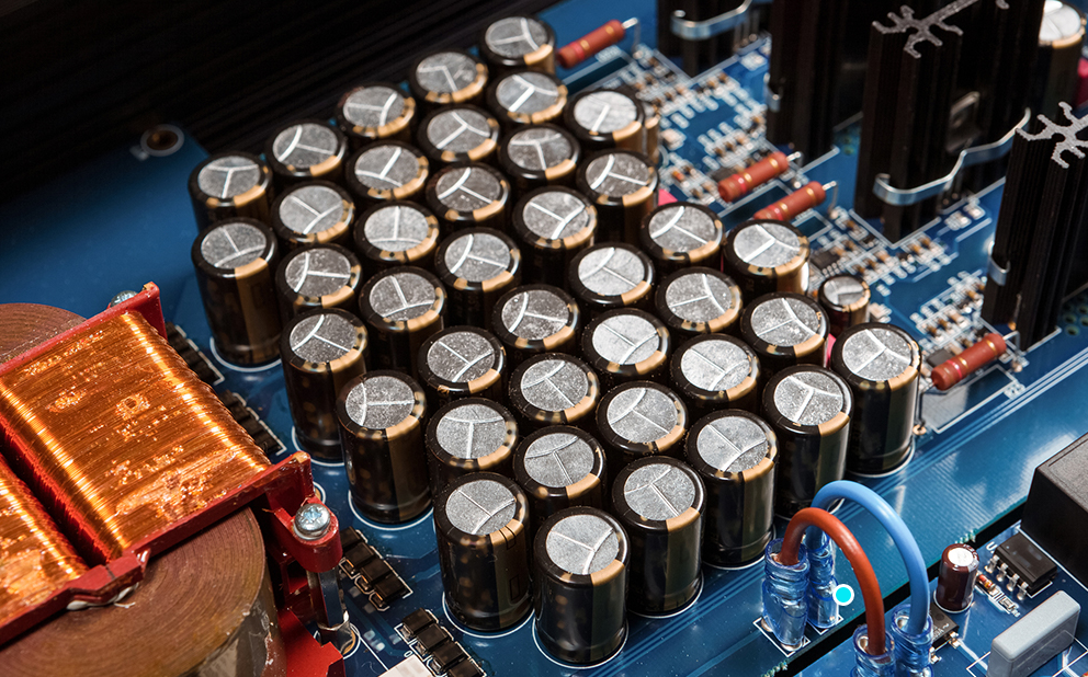
First, consider whether the ambient temperature for electrolytic capacitors meets the requirements, and secondly, position the capacitors as far away from heat-generating areas as possible to prevent the internal liquid electrolyte from drying out.
MM32 MCU
Lingdong Micro ClassroomCompilation
(Click the title to view the original text)
MM32 Application Notes
How to configure MM32 system clock?
Getting Started with MM32 GPIO
MM32 External Interrupt Line EXTI
MM32 UART Interrupt Communication
MM32 Control 4-Wire Resistive Touch Screen via ADC
MM32 Internal Temperature Sensor and High-Temperature Clock Calibration Configuration
MM32 Power Management
MM32 Programmable Voltage Detector (PVD)
MM32 Low Power Mode
MM32 Wake Up via UART in STOP Mode
MM32 MCU BKP Backup Register
MM32 FLASH Operations
MM32 MCU Encryption Methods
MM32 SysTick Timer
MM32 Timer Operations
MM32 Timer Pulse Counting
MM32 TIM Encoder Mode
MM32 Timer Capture Comparator Output
MM32 MCU Complementary PWM Output with Dead Zone and Brake Function
MM32 Six-Step PWM Output
MM32 Breathing Light Function
MM32 Timer Periodically Trigger ADC Sampling (Recovery)
MM32 Independent Watchdog (IWDG)
MM32 Window Watchdog (WWDG)
MM32 DAC Output Design Based on PWM
MM32 Comparator Interrupt
Implementing Partial Code Execution in RAM in KEIL Environment
MM32 IAP Interrupt Vector Table Redefinition
MM32 IAP Upgrade – APP Section
MM32 MCU Programming Experience Sharing
MM32 Application Notes – Color Recognition Application
MM32SPIN2x Motor Specific MCU Features
Automatic Commutation Shielding Function Configuration
PWM Module Usage – Current Compensation and Protection
Hardware Divider and Square Root
Voltage Comparator
UART Module Bit9 Function
CRC Calculation Unit
ADC DMA Module Configuration
I2C Functionality
SPI Functionality
Independent Watchdog Low Power Wake-up
Power Management for Highly Integrated Products
MM32SPIN Motor/Power Dedicated Chip Application Solutions
Electric Tool Section
Vacuum Cleaner Section
Electric Vehicle Section
Robot Servo Section
Range Hood Section
Fan Section
Sensorless Square Wave Drive Application Solution – Medium and Small Power Water Pump
Sensorless Sine Wave Drive Application Solution – Handheld Vacuum Cleaner
Brushed Motor Drive Application Solution – Robot Servo
MM32-LINK User Guide
MM32 Devkit Setup Quick Installation
MM32-LINK Debugger Quick InstallationMM32 Program Quick Start
MM32-LINK Password Setting
Remote Authorized Programming
Programming Rules Setting
Read-Write Protection Operation
Programming Count Function
Serial Port Function and Hardware Connection Methods Introduction
Usage Tips
MM32W Wireless MCU Series Product Application Solutions
Module and AT Commands
Bluetooth Development Kit Introduction
Interrupt-Based Example
Blocking Example
Low Power BLE Bluetooth Applications
Interface Function Calls
Custom Services and Characteristics
Custom AT Commands
Smart Color Remote Control Light Solution
Bluetooth Selfie Stick Solution
Temperature and Humidity Monitoring Instrument Solution
Bluetooth Smart Lock Solution
Data Transparent Transmission
Data Acquisition Instruments
Shell Debugging Tutorial Based on MM32 MCU
Shell Debugging Tutorial Based on MM32 MCU (Part One)
Shell Debugging Tutorial Based on MM32 MCU (Part Two)
Shell Debugging Tutorial Based on MM32 MCU (Part Three)
MM32 USB Function Learning Notes
USB HID Devices
WinUSB Devices
Virtual Serial Port CDC
Simulated USB Drive
USB Composite Devices
WebUSB Functionality
WebDFU
Virtual Serial Port CDC
Application Solutions Sharing for MM32 MCU Epidemic Prevention Products
Handheld Single Point Thermometer
Fixed Multi-Point Thermometer
Portable Refrigerator
Blood Oxygen Monitor
Monitor
Ventilator
Infusion Pump
Home Air Conditioner with Variable Frequency
OS Porting and Application Based on MM32 MCU
OS Porting and Application Based on MM32 MCU
New Project Creation on AMetal Platform
AMetal LED Light Control
AMetal Serial Communication
AMetal I2C Operation
AMetal SPI Operation
AMetal ADC Sampling Configuration
AMetal Timer Configuration
AMetal CAN Communication Configuration
AMetal Comprehensive Example
RT-Thread Porting and Multi-Task Implementation
RT-Thread Key Control Implementation
RT-Thread UART Data Transmission and Reception
RT-Thread Memory Management
RT-Thread Thread Management
RT-Thread Power Management
RT-Thread Shell Usage
RT-Thread CPU Utilization Statistics
RT-Thread Interrupt Management (1)
RT-Thread Interrupt Management (2)
RT-Thread RTC Calendar
ThreadX Introduction
MM32F013x
UART Hardware Baud Rate Adaptation
UART LIN Communication
UART 9bit Communication
UART Multi-Processor Communication
UART Inverted Polarity Communication
UART Single-Wire Half-Duplex Communication