Click the above“Mechanical and Electronic Engineering Technology”to follow us
This article introduces three experiments: lighting a single LED, flashing a single LED, and running lights using the 51 microcontroller, along with programming in C language and assembly language.
1. Circuit Diagram Used
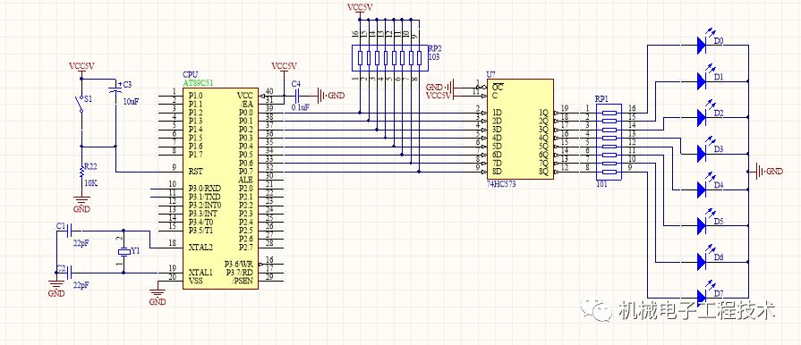
As shown in the figure, the 51 microcontroller connects 8 light-emitting diodes to port P0 through a latch 74HC573. Since the cathodes of the LEDs are grounded, they can be lit by providing a high level to the anodes, which requires port P0 to output a high level.
Note:
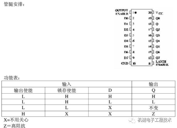
74HC573: The 74HC573 contains eight octal 3-state non-inverting transparent latches and is a high-performance silicon gate CMOS device. The SL74HC573 has the same pinout as the LS/AL573. The device’s inputs are compatible with standard CMOS outputs, and with pull-up resistors, it can work with LS/ALSTTL outputs.
2. Lighting a Single LED
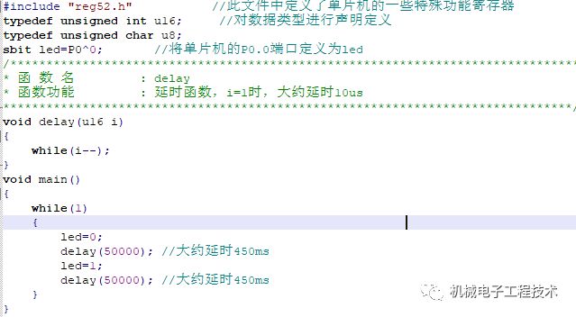
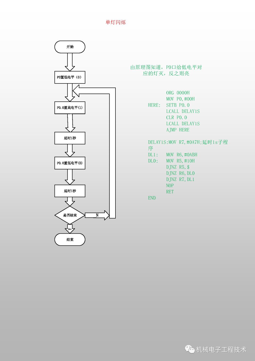
3. Flashing a Single LED
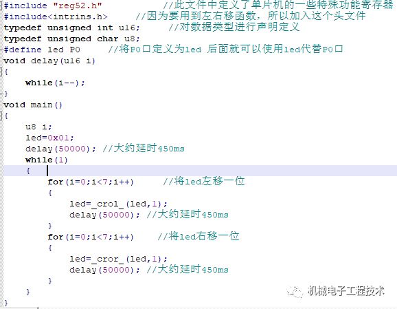
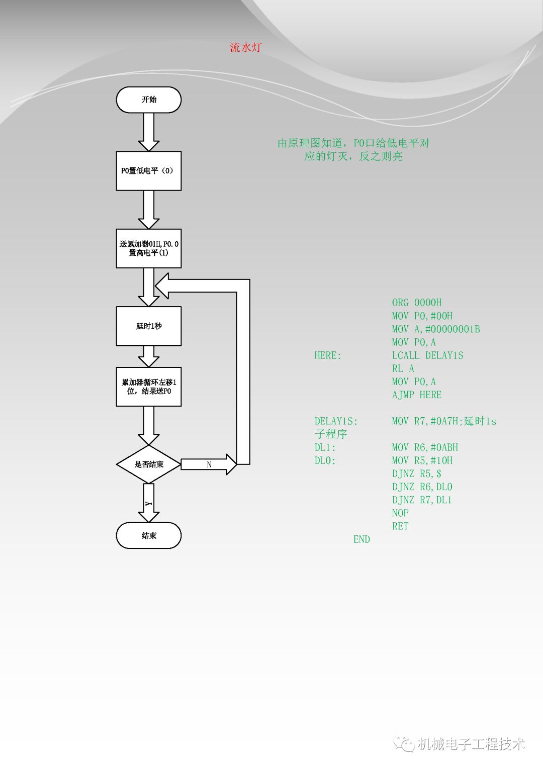
4. Running Lights
Running lights consist of a group of lights that illuminate and extinguish in a predetermined order and timing under the control of a system, creating a visual effect. Many storefronts and signs on the streets have running lights installed, making them look more attractive.
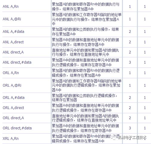
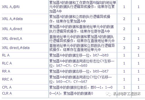
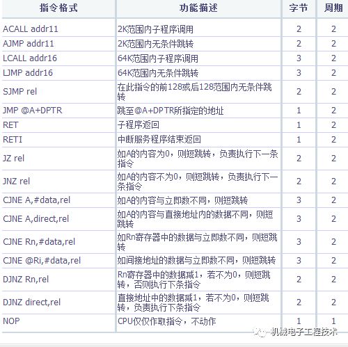
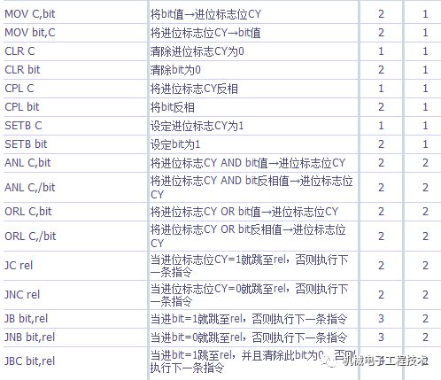
Appendix:
For the microcontroller to perform calculations and control effectively, it must be supported by software. Software refers to various programs. Only by correctly loading various programs into the microcontroller can it operate effectively. The microcontroller can perform automatic calculations and control because commands that implement calculations and control steps are stored in memory in the form of instructions. Under the control of the CPU, the microcontroller retrieves these instructions one by one, translates, and executes them. For example, in the simple operation of adding two numbers, once the numbers are stored in memory, the following steps are required:
Step 1: Retrieve the first number from its storage unit and send it to the arithmetic unit.
Step 2: Retrieve the second number from its storage unit and send it to the arithmetic unit;
Step 3: Add them;
Step 4: Send the result to the specified storage unit in memory.
All these operations of retrieving, sending, adding, and storing are performed using commands. The various operations that the computer must execute are written down in the form of instructions. But how can these operations be identified and executed? This is determined by the instruction set provided by the designers of the microcontroller during its design. Each instruction corresponds to a basic operation; the entire set of instructions that a microcontroller can execute constitutes its instruction set. Different types of microcontrollers have different instruction sets.
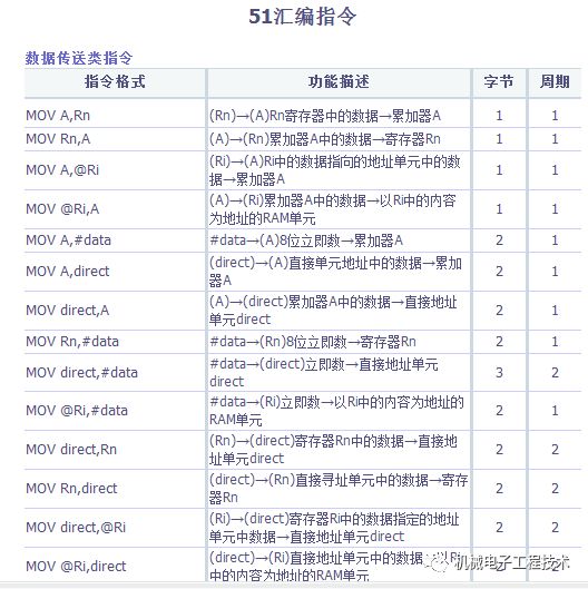
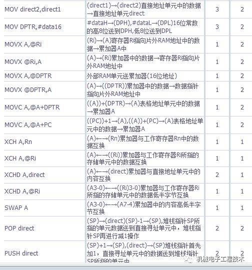
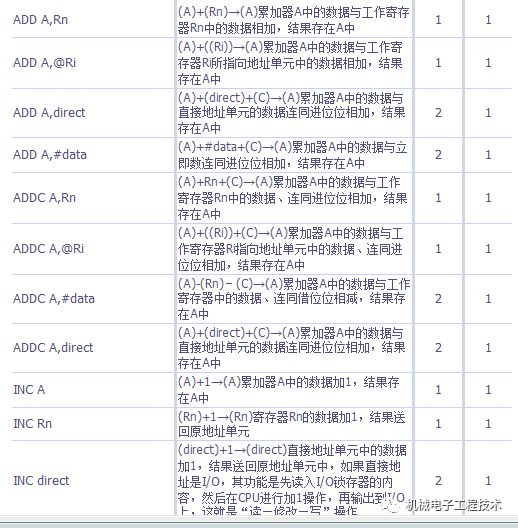
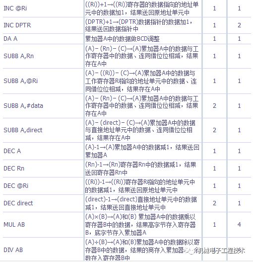
When using a microcontroller, one must compile a series of instructions to solve the problem beforehand. These instructions must be ones that the selected microcontroller can recognize and execute. The instruction program compiled by the microcontroller user to solve their problem is called the source program. Instructions are typically divided into operation codes (Opcode) and operands. The operation code indicates what operation the computer should perform, i.e., the function of the instruction; the operand indicates the number involved in the operation or the address of the operand (the location number where the operand is stored). Because the microcontroller is a programmable device, it only “understands” binary code (0, 1). For the microcontroller to function, all instructions in the microcontroller system must be represented in binary code. For example, in Intel’s MCS-51 series microcontrollers, the instruction code for retrieving a number from memory to the CPU’s accumulator (a special register that participates in calculations and stores results) is 74H, the code for adding the accumulator content with an immediate number is 24H, and the code for sending the accumulator content to internal RAM storage is F6H~F7H, etc. These instructions are represented in hexadecimal format to denote binary machine code.
The word length of the MCS-51 microcontroller is 8 bits. Sometimes, a single byte is insufficient to express certain operations. Therefore, there are both single-byte and multi-byte instructions in the instruction set. Machine code consists of a series of 0s and 1s, which have no obvious features, making them hard to memorize, difficult to understand, and prone to errors. Therefore, writing programs directly in machine code is very challenging. As a result, people use some mnemonics—usually English abbreviations of instruction functions to replace operation codes; for example, in MCS-51, data transfer is often represented by MOV (abbreviation for Move), and addition is represented by Add (abbreviation for Addition). This way, each instruction has a clear action characteristic, is easy to remember and understand, and is less prone to error. Programs written using mnemonics are called assembly language programs. However, programs written in mnemonics are easy for humans to understand, but the microcontroller only recognizes binary machine code. Therefore, to allow the microcontroller to “understand” assembly language programs, they must be converted into programs composed of binary machine code. This conversion process is called “assembly.” Assembly can be achieved using manual lookup methods or with the help of a PC through a so-called “cross-assembler”. Once the user program composed of machine code is “loaded” into the microcontroller and the microcontroller is “activated,” it can execute the tasks specified by the input program.

To learn more
Scan the code to follow