Common Faulty Components on PCBs
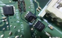
Common Faulty Components on PCBs

The failure caused by capacitor damage is the highest in electronic devices, especially with the failure of electrolytic capacitors being the most common. Capacitor damage manifests as: reduced capacity, complete loss of capacity, leakage, and short circuit.Capacitors play various roles in circuits, and the faults they cause are also characterized differently: in industrial control circuit … Read more
How To Measure Capacitor Quality With A Multimeter

How To Measure Capacitor Quality With A Multimeter

Siemens Comprehensive + Portal + EPLAN Electrical Drawing Video Recordings Available for Sale at Low Package Prices! Chuangkong Education Siemens Comprehensive Course Introduction 1. Measuring Capacitor Quality with a Pointer Multimeter To measure the quality of a capacitor, it is best to use a pointer multimeter, which is more intuitive. Below, we will use the … Read more

12 Details for PCB Layout

12 Details for PCB Layout

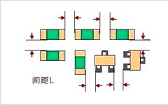
1. Spacing Between SMDs The spacing between SMDs should neither be too large (which wastes PCB area) nor too small to avoid solder paste printing adhesion and difficulties in soldering repairs. The spacing can refer to the following specifications: ■ Same component: ≥ 0.3mm■ Different components: ≥ 0.13×h+0.3mm (h is the maximum height difference between … Read more

25 Essential Electrical Principles You Need!

25 Essential Electrical Principles You Need!

1. Regulations for Wiring Single-Phase Power Outlets There are various types of single-phase outlets, commonly divided into two-hole and three-hole types. Two holes are arranged side by side, while three holes form a “T” shape. Next to the wiring holes are marked letters: L for live, N for neutral, and E in the center of … Read more

Why Connect Ground Capacitors to MCU Crystals?

Why Connect Ground Capacitors to MCU Crystals?

Many electronic engineers are puzzled by the practice of connecting a ground capacitor on each side of the MCU crystal during design. Even after researching, they find little explanation in books, often mentioning that ground capacitors provide stability or are considered load capacitance, but without in-depth analysis. So today, I will explain why this is … Read more

How to Calculate the Value of Capacitor C1 in Microcontroller Reset Circuit

How to Calculate the Value of Capacitor C1 in Microcontroller Reset Circuit

[Question] How to calculate the value of capacitor C1 in the microcontroller reset circuit? I need the specific formula and explanation! Urgently needed! [Incorrect Answer] Taking the 51 microcontroller as an example: The reliable reset time for the microcontroller must be greater than 2 machine cycles. If using a 12MHz crystal oscillator, the reset time … Read more

Summary of PCB Circuit Board Symbol Meanings

Rx is a resistor, there are many resistors in the circuit diagram, numbered sequentially, R1, R2… Cx is a non-polar capacitor, anti-interference capacitor at the power input terminal. IC is an integrated circuit module. Ux is an IC (integrated circuit component). Tx is a test point (for factory testing). Spk1 is a Speaker (buzzer, horn). … Read more

Meaning of Letters on Electronic Components in Circuit Boards

Meaning of Letters on Electronic Components in Circuit Boards

Rx is a resistor. In circuit diagrams, there are many resistors, numbered sequentially, R1, R2… Cx is a non-polar capacitor, a noise filter capacitor at the power input. IC is an integrated circuit module. Ux is an IC (integrated circuit component). Kx varies by manufacturer and defines different component libraries. Tx is a test point … Read more

Meaning of Letters on Circuit Boards (PCBs)

Meaning of Letters on Circuit Boards (PCBs)

Rx is a resistor. In circuit diagrams, there are many resistors, numbered sequentially, such as R1, R2, … Cx is a non-polar capacitor, used as an anti-interference capacitor at the power input. IC refers to integrated circuit modules. Ux is an IC (integrated circuit component). Kx is ??? different manufacturers have different definitions in their … Read more

Frustration with Circuit Board Troubles: A Bold Dissection!

Frustration with Circuit Board Troubles: A Bold Dissection!

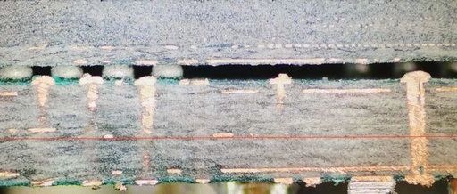
The image below marks the position of the DDR2 chips that were cut open. We can see that there are dense traces inside the new foam. The BGA solder balls are marked in red. This is a 6-layer board, with the positions of the TOP, BOTTOM, and the four internal electrical layers already indicated. Since … Read more