☝Click the blue text above to follow me.
I hope the suggestions at the end of this article will be helpful to you.
One morning, I passed by a coffee stand at a construction site and saw an experienced electrician demonstrating ladder diagrams to two young men. To put it simply, it was practical. I am not a complete stranger to PLCs; I have seen them in action in 25 countries. Truly, there are machines buzzing everywhere, and after a whole day, my hands are sore, but it’s worth it.
Let’s put it this way: to get started with PLCs, you don’t need anything fancy. First, understand the basic instructions before diving deeper; otherwise, it’s like building a house in the air. In other words, you need to learn to run before you can walk. Below, I will explain these instructions in a way that both you and I can understand, just like the experienced electrician would.
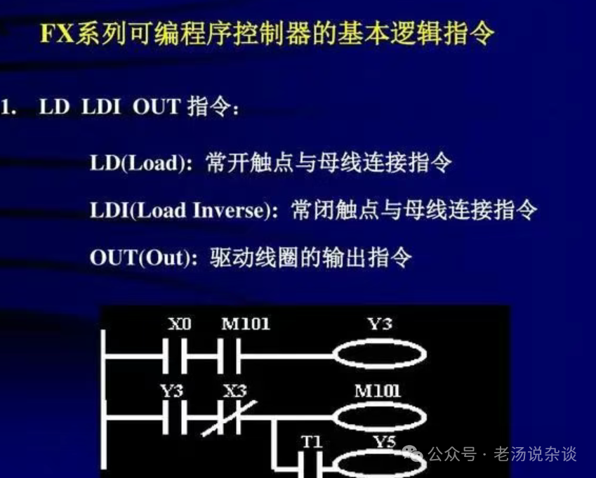
1. Switch Input Basics: LD and LDIThese two are like gatekeepers, similar to opening and closing a circuit.
- LD: Normally Open Contact, true when activated
- LDI: Normally Closed Contact, the oppositeIn other words, if you want a button to activate, it’s LD; if you want it to deactivate, it’s LDI. It’s exhausting, really. The logic is simple, but in practice, connections often get reversed, and when the wiring is messy, people get confused. I once saw this at a brewery in Prague, where they switched between cleaning and production using these two. Without them, it’s hard to imagine.
2. Series Connection: AND and ANDITo put it simply, AND is true only when all conditions are true, while ANDI uses a normally closed contact to lock a position.
- AND: Multiple conditions must be satisfied simultaneously
- ANDI: One condition is the opposite logicFor example, if you want a motor to run, all safety conditions must be locked in place first. Safety first; don’t test with your fingers whether it will run or not.
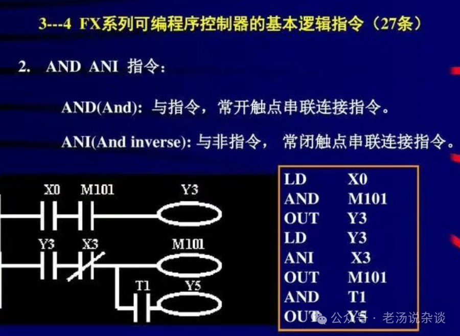
3. Parallel Connection: OR and ORII initially wanted to write something complex, but let’s keep it straightforward.
- OR: Any one condition being true is sufficient
- ORI: Uses normally closed contacts in parallelFor instance, in an emergency stop reset, you can press either the panel button or a remote one; as long as one signal is received, the system will allow operation. This is very common.
4. Output: OUTSimply put, if there’s no output, all your thoughts are in vain.
- OUT: Writes the current logic to a coil or positionIf you want to turn on a light or pull a relay, you need to write M10.0. Remember, OUT is the hammer, the final decision. I think this is simple, but it’s easy to write it incorrectly multiple times, leading to confusion about which side has the final OUT. Be careful.
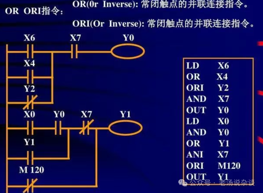
5. Latching: SET and RESETAh, these two are memory elements and also sources of trouble.
- SET: Sets the position to true
- RESET: Resets to zeroThe experienced electrician said they must be paired; if you only SET without RESET, the lights will stay on indefinitely, which can lead to trouble during night inspections. Really, it’s important to develop the habit of knowing where to set and where to reset, and to clarify the conditions; otherwise, you’ll spend a long time troubleshooting.
6. Timers: TON and TOFTime is like a stopwatch; it sets the rhythm.
- TON: On-delay timer, true only after a set time
- TOF: Off-delay timer, remains true for a while after being turned offFor instance, when starting a cleaning pump, you first fill the pipeline; TON for one second before starting the main pump ensures smooth operation. TOF is like a fan that continues to blow for ten seconds after the main motor is turned off to allow for cooling. In short, it allows the equipment to breathe.
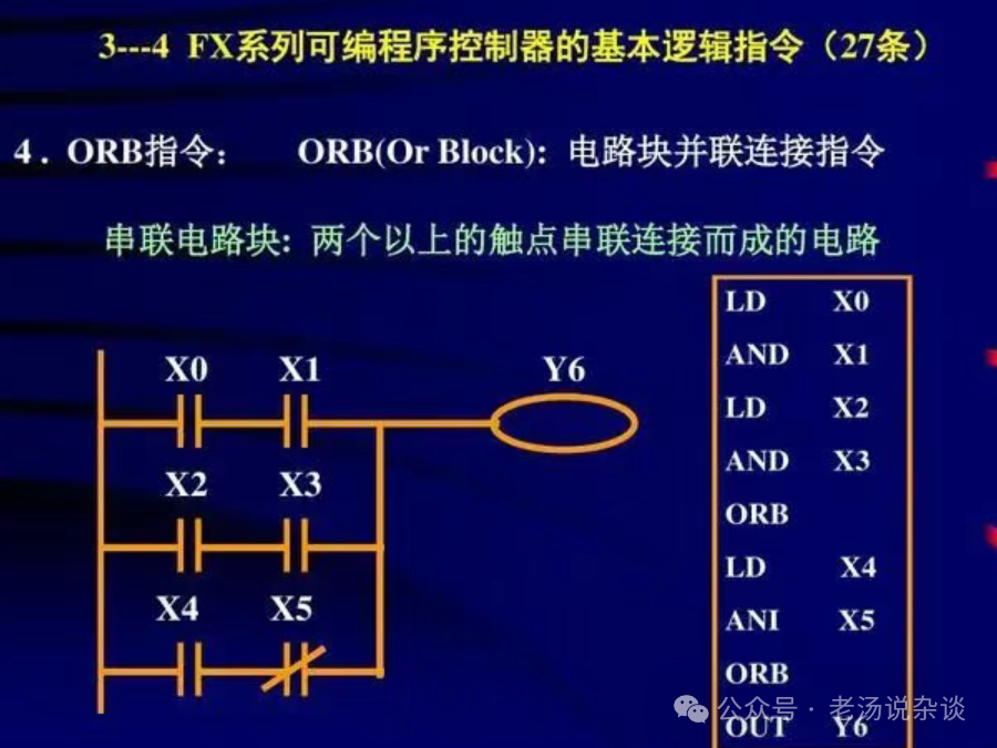
7. Counters: CTU, CTD, CTRCount to know how many times something has been done.
- CTU: Counts up to a preset output
- CTD: Counts down to zero
- CTR: Can count up or downI saw this at a bottling line in Turkey, where there are 24 bottles in a box. CTU counts to 24, and then the box sealing gun activates accurately. Be careful with vibrations; otherwise, one bottle might trigger two pulses, leading to confusion on site.
8. Data Transfer: MOV and Comparison Instruction CMPData also needs to be moved.
- MOV: Moves data from A to B
- CMP: Compares values for equality, greater than, or less thanIn fact, the analog values you get from sensors need to be MOVed to registers first, then scaled, and then CMP compared with thresholds. If it matches, an alarm is triggered. In short, don’t judge directly from raw values; noise can make you dizzy.
9. Rising and Falling Edges: P_TRIG and N_TRIGIt’s like taking a snapshot; you capture a moment.
- Rising Edge: Pulses only when transitioning from 0 to 1
- Falling Edge: Pulses only when transitioning from 1 to 0Indeed, if you press a momentary button, it should only add 1 each time; if you don’t use edges, it will continuously add while held down, which is not the PLC’s fault. In short, edge triggers should be placed where they belong, not scattered globally.
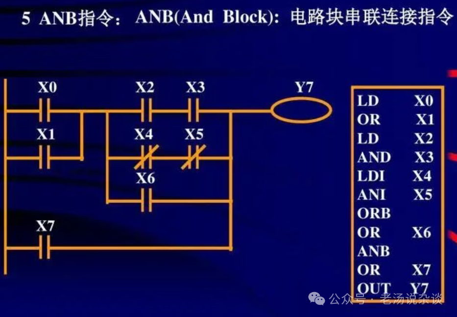
10. Subroutines and Calls: SUB, CALL, RETIn a large project, it’s essential to modularize.
- SUB: Subroutine, modularization
- CALL: Call to execute
- RET: ReturnI saw in Germany how they modularized alarms, motion control, and communication into SUBs, making everything clear. In short, when you maintain it later, you’ll thank your past self.
That said, knowing these ten basic instructions doesn’t mean you know how to use them. In practice, there are three bottom lines that I think must be ingrained in your mind:
- Safety chain precedes logic chainBefore a motor can run, safety conditions must be locked in place; there’s no negotiation.
- Debouncing and filteringMechanical contact bounce and sensor noise should not be ignored.
- Status visualizationWhether it’s lights or HMIs, make sure people can easily see the current status.
Some students jump straight to PID, thinking about cloud communication and remote OTA. In fact, these ten basics are like the Phillips and flathead screwdrivers; first, get familiar with them before discussing analog scaling, race conditions in edge detection, redundancy, and fault bypassing. Is it tiring? Yes, but it’s solid.
I’m forty years old, and while waiting for stars to finish their makeup on set, I still look at other people’s electrical cabinets, admiring the neat wiring. An experienced electrician handed me a zip tie and said, “You see, when learning PLCs, first secure this bundle of wires; only then will the logic not get messy.” Really?! I laughed; he was right.
Finally, here’s a simple routine: every time you write a piece of logic, ask yourself three questions:
- Simply put, are the conditions clear? Is there any reverse logic?
- In fact, could the output be overridden elsewhere?
- How should the state be restored or maintained after power cycling?
I initially wanted to post the code, but I think the language is clear; you can write anything smoothly. Truly, once you understand these concepts, it’s not too late to delve deeper into learning PLCs. Right? Right? Right?

END
Welcome to like, share, and view to encourage me
If you find this article useful, please consider a small appreciation, and I will share more with you next time~
👇👇Follow me👇👇