1. Introduction to Application Scenarios
In industrial control and teaching practice, PLC light control is a fundamental and typical case. This article focuses on the Siemens S7-200 SMART PLC to implement the alternating flashing function of eight LED lights in two groups, suitable for scenarios such as indicator light control and running light simulation.
2. Hardware Configuration and Wiring
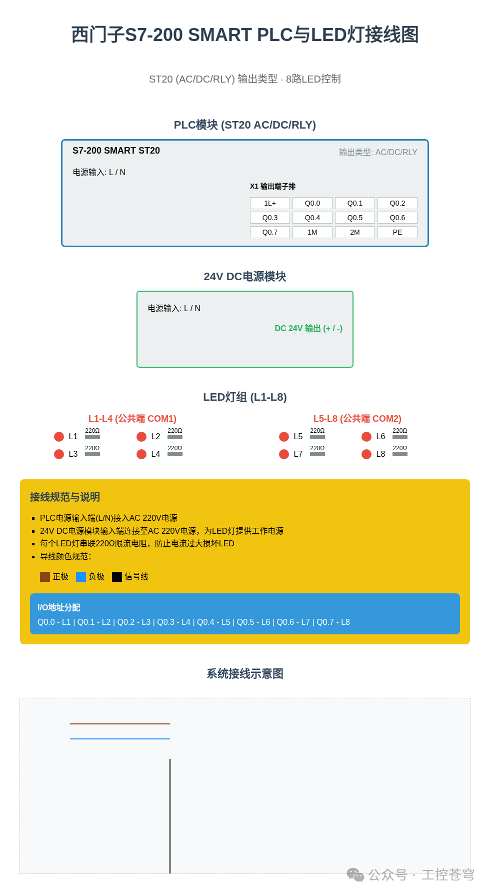
Core Components: S7-200 SMART ST20 (AC/DC/RLY), 8 LED lights (24V), 220Ω current-limiting resistor, DC 24V power supply.
Wiring Points:
• The light groups are divided into two groups: L1-L4 (Q0.0-Q0.3) share COM1, and L5-L8 (Q0.4-Q0.7) share COM2.
• Each group of LEDs connects the common terminal to the DC 24V negative, and the PLC output terminal connects to the positive terminal of the LED through the current-limiting resistor.
• AC 220V powers the PLC, while the DC 24V module provides power to the light groups.
3. Core Program Design
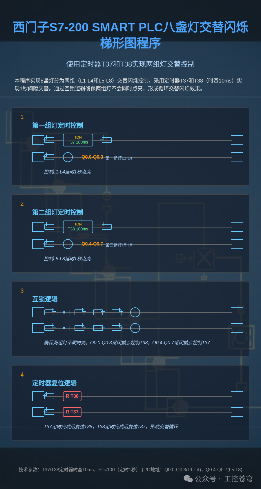
Two timers (T37/T38) are used to achieve 1-second alternating control, with the key logic as follows:
Network 1: T37 times 1 second to control the output of the first group of lights.
TON T37, 100 // Time base 10ms, PT=100 means 1 second = Q0.0, Q0.1, Q0.2, Q0.3 // Output of the first group of lights
Network 2: T38 times 1 second to control the output of the second group of lights.
TON T38, 100 = Q0.4, Q0.5, Q0.6, Q0.7 // Output of the second group of lights
Interlocking Logic: Ensure that the two groups of lights do not light up simultaneously through normally closed contacts, with timers alternating reset.
4. Debugging and Expansion
Debugging Points:
• Check whether the COM terminal grouping is correct to avoid incorrect common terminal connections that prevent the light groups from lighting up.
• The timer time base should be set to 10ms (default), and the PT value of 100 corresponds to 1 second.
• Monitor the Q output status online and adjust the flashing frequency by modifying the PT value.
Application Expansion:
• Add a counter to control the number of flashes.
• Modify timer parameters to achieve fast and slow alternating effects.
• Expand to 16 lights to achieve more complex running light effects.
5. Conclusion
This example achieves the alternating flashing control of eight lights through simple timer interlocking logic. Mastering this method allows for quick expansion to various timing control scenarios, making it a classic case for PLC introductory learning. In practical applications, attention should be paid to matching the output point capacity, and high-power loads may require additional intermediate relays.
Don’t forget to like, share, and forward!