1. Overview of High-Speed Counters
The S7-200 SMART PLC integrates hardware high-speed counters that operate independently of the CPU scan cycle. The standard CPU (firmware version V2.3+) supports 6 channels of high-speed counters, while the compact CPU supports 4 channels. The C-type CPU has a maximum counting frequency of 100kHz, and the S-type CPU reaches 200kHz, depending on the model and firmware version.
2. Classification of Operating Modes (8 Types)
Based on the type of input signal and control method, the modes are divided into four main categories:
| Mode Group | Mode Number | Description | Key Features |
|---|---|---|---|
| Single-phase Internal Direction | 0 | No external reset | Direction controlled by SMB37.3, 1=increment, 0=decrement |
| 1 | With external reset | Supports external reset signal (I0.4 high/low level effective) | |
| Single-phase External Direction | 3 | No external reset | Direction controlled by external input (e.g., I0.1) level |
| 4 | With external reset | External direction + reset function | |
| Dual-phase Increment/Decrement Counting | 6 | No external reset | Increment/decrement counting pulses controlled by two inputs |
| 7 | With external reset | Dual-phase input + external reset | |
| A/B Quadrature Counting | 9 | No external reset | A/B phase quadrature input, supports 1X/4X frequency multiplication |
| 10 | With external reset | Quadrature input + external reset (Z phase) |
3. Key Technical Parameters
-
Input Filter Time
Must be set in the system block, default 6.4ms supports only 78Hz, high-speed applications should be changed to 0.2~3.2μs (corresponding to 200kHz).
-
Interrupt Events
- Current value = preset value (events 12-16)
- Direction change (events 27-28)
- External reset (event 28)
Address Allocation
- Control byte: SMB37 (HSC0), SMB47 (HSC1), etc.
- Current value: SMD38 (HSC0), HC0 (read-only)
- Preset value: SMD42 (HSC0)
4. Typical Application Wiring
Taking the A/B quadrature encoder (mode 10) as an example:
- A phase → I0.0 (Clock A)
- B phase → I0.1 (Clock B)
- Z phase → I0.4 (Reset)
- Encoder power supply: 24V DC
5. Programming Key Points
-
Initialization Steps
plaintext
// HSC0 mode 10 initialization example
SMB37 = 16#FC; // Enable counting, update current value/preset value<span>SMD38 = 0; // Clear current value</span><span>SMD42 = 1000; // Preset value 1000</span><span>HDEF 0, 10; // Define HSC0 as mode 10</span><span>ATCH INT_0, 12; // Bind CV=PV interrupt</span><span>ENI; // Enable global interrupts</span><span>HSC 0; // Start counter</span>
-
Interrupt Handling
Update preset value or perform reset operation in the interrupt program.
6. Firmware Version Differences
- V2.3+: Standard CPU supports 6 channels of HSC, new frequency measurement mode added
- V2.8+: Supports 16 channels of PID, ST60 pulse axis expanded to 4 channels
Note: HSC1/HSC3 only support mode 0, input points cannot be shared with other high-speed functions.
1. Hardware Wiring Diagram
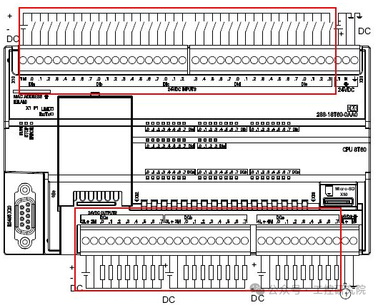
Figure 1: Wiring diagram for HSC0 mode 10 (A/B quadrature with reset), I0.0 connected to A phase, I0.1 connected to B phase, I0.4 connected to reset signal
2. Operating Mode Timing Diagram
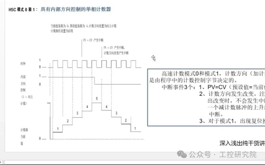
Figure 2: Timing waveform of single-phase counter with internal direction control (mode 0/1), showing counting direction switch and interrupt trigger points
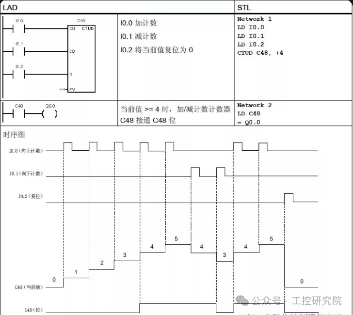
Figure 3: 4X frequency working principle of A/B phase quadrature counting (mode 9/10), A/B phase pulse phase difference of 90° for direction determination
3. Programming Example Screenshots
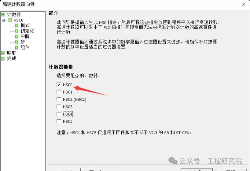
Figure 4: Step interface for configuring HSC0 using STEP 7-Micro/WIN SMART wizard, including mode selection and parameter settings
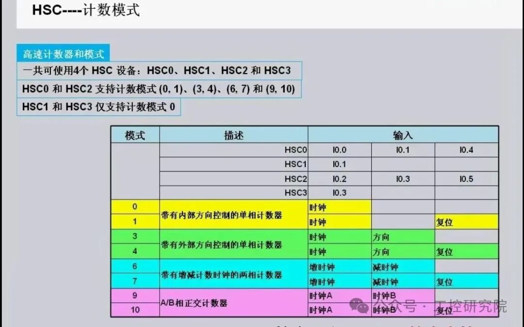
Figure 5: Example of HSC initialization subroutine, including control byte settings, interrupt binding, and counter start command
8. Mode Selection Decision Tree
mermaid
graph<span> TD</span><span> A</span><span><span>[Select Counter Type]</span></span><span><span>--></span></span><span><span>|Single-phase Input|</span></span><span> B</span><span><span>(Internal Direction Control)</span></span><span> A </span><span><span>--></span></span><span><span>|Single-phase Input|</span></span><span> C</span><span><span>(External Direction Control)</span></span><span> A </span><span><span>--></span></span><span><span>|Dual-phase Input|</span></span><span> D</span><span><span>(Increment/Decrement Counting)</span></span><span> A </span><span><span>--></span></span><span><span>|Quadrature Encoding|</span></span><span> E</span><span><span>(A/B Phase Counting)</span></span><span> B </span><span><span>--></span></span><span> F</span><span><span>[Mode 0: No Reset]</span></span><span> B </span><span><span>--></span></span><span> G</span><span><span>[Mode 1: With Reset]</span></span><span> C </span><span><span>--></span></span><span> H</span><span><span>[Mode 3: No Reset]</span></span><span> C </span><span><span>--></span></span><span> I</span><span><span>[Mode 4: With Reset]</span></span><span> D </span><span><span>--></span></span><span> J</span><span><span>[Mode 6: No Reset]</span></span><span> D </span><span><span>--></span></span><span> K</span><span><span>[Mode 7: With Reset]</span></span><span> E </span><span><span>--></span></span><span> L</span><span><span>[Mode 9: No Reset]</span></span><span> E </span><span><span>--></span></span><span> M</span><span><span>[Mode 10: With Reset]</span></span>
High-Speed Counter Mode Selection Decision Process
 Like, Follow + Share!