Embedded Communication Protocol: How Many IIC Interview Questions Can You Answer?
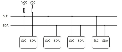
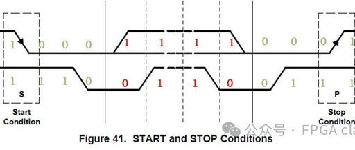
1. What is the Validity of IIC Protocol Data? (1) Data Transmission Format Start and Stop Conditions: When the SCL line is high, a transition from high to low on the SDA line indicates a start condition; when SCL is high, a transition from low to high on the SDA line indicates a stop condition. … Read more