1. Understanding I2C Communication
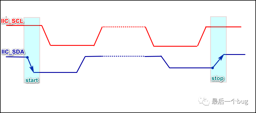
Many friends often feel confused when developing the IIC communication protocol. On one hand, it’s normal to forget related knowledge if it hasn’t been used for a long time. However, it can be quite troublesome to keep looking at the communication timing diagrams, such as the starting level conditions, stopping level conditions, and data hold/update conditions, etc.
Although the waveform requirements for IIC communication are not too different for each device, the tolerance for IIC communication timing is very high, so basically, the conventional range of communication parameters and drivers are universal.
The transmission process of IIC data is controlled by the SCL communication clock pulses, where the master device actively changes the bus level to allow the slave to detect and receive the data. After the slave receives the data, it then actively pulls down the SDA line as an acknowledgment signal to notify the master; if it does not pull down, it indicates no acknowledgment.
Many friends previously did not understand how the IIC master detects the slave’s acknowledgment, as it seems that the waveform on the SDA line looks like it is sent by the master. Therefore, when analyzing communication waveforms, it is essential to distinguish whether the signal is being processed by the master or the slave.
For communication applications, what’s important is not the so-called level changes; of course, they are not unimportant, as sometimes unstable communication requires analysis from the original waveform. However, most application developers need to understand how to transmit data frames and master the process and method of data frame transmission.
Different manufacturers have slight variations in data frames, such as 7-bit addresses, 8-bit addresses, and 10-bit addresses, but overall they are quite similar. You can refer to the respective chip manuals for learning; here we will introduce the most commonly used 7-bit address:
IIC is a master-slave communication method, where the communication initiator is the master, and it is primarily familiar with three types of data frame transmission processes:
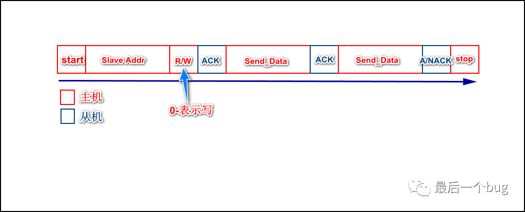
1. Single or Continuous Write Data to Slave
Note that the above is merely the data frame transmission, similar to our usual serial communication, and the meaning of the data within the communication data domain is agreed upon by both parties, which is referred to as the formulation of the application layer protocol.
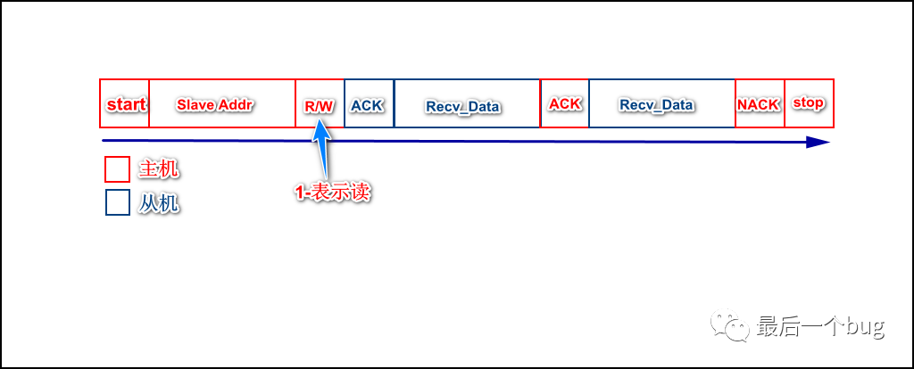
2. Single or Continuous Read Data from Slave
In the data reading process, the read/write flag sent by the master changes, and the slave actively controls the bus to send data to the master, which then acknowledges, exactly opposite to writing data in IIC.
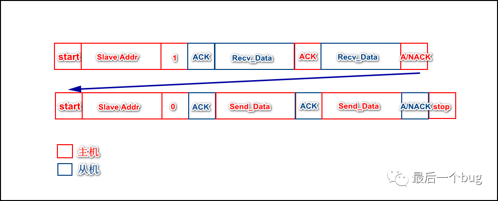
3. Read/Write Switching During Communication
When read/write switching is needed during communication, it does not require sending a stop signal; instead, after acknowledgment, the master should resend the start signal along with the slave address and read/write state, followed by data processing.
3. Don’t Forget Pull-Up Resistors for IIC Communication
Do not forget to pull up the communication IO for the IIC bus. The pull-up mainly ensures that the signal line maintains a high level when idle, which is logic 1.
At the same time, the IIC bus adopts an open-drain output architecture, where devices on the communication line can pull the line level low, i.e., logic 0; however, they cannot actively pull the line high to logic 1, so pull-up is essential.
Therefore, to ensure that sufficient drive capability is provided on the communication line without causing signal distortion, the selection of the pull-up resistor value is particularly important.
4. How to Choose Pull-Up Resistors?
How to choose pull-up resistors? There are many influencing factors:
1. Length of the Communication Bus
Usually, the longer the communication line, the slightly larger the resistor should be.
2. Material of the Communication Bus
If the bus provides a high capacitive load, the resistance should be appropriately reduced to speed up the signal change time.
Appropriately reduce the pull-up resistor to increase drive current and speed up the level response time.
In summary, specific situations should be analyzed and a compromise should be made in selecting pull-up resistors, and finally, attention should be paid to level matching to avoid damaging the chip.
Copyright belongs to the original author. If there is any infringement, please contact for deletion.
I used this technology to eliminate thousands of lines of if else!
Kirin 9000s is not from SMIC, but…
Words that programmers are most likely to misread; I exploded when I heard status.