Timing is very important for digital circuits; it can be said that timing is the foundation for the normal operation of digital circuits. When it comes to timing, it generally refers to the programming methods of programmable devices. In microcontroller programming, it is necessary to write programs based on the timing of the controlled chip, implementing the timing specified in the chip manual with code to facilitate communication between the microcontroller and the chip. Below, I will briefly introduce how to understand timing using the timing diagrams of several commonly used chips.
IIC Communication Start/Stop Timing
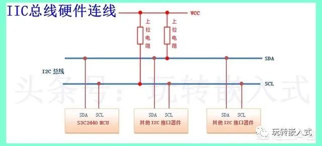
IIC is a common communication method between chips, also known as I2C, suitable for short-distance communication within a PCB. It consists of two lines and can connect multiple devices with different addresses. The hardware connections are shown in the figure below.
When communicating via IIC, a start signal must be sent first, and an end signal must be sent when the data transmission is complete. The timing diagrams for the start and end signals are provided in the device manual, and during programming, C language code must be used to implement the start and end timing, as shown in the timing diagram below.
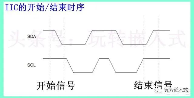
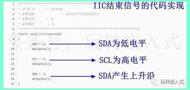
SCL is the clock line for IIC, and SDA is the data line. The way SDA data is transmitted must follow the specific SCL timing. From the diagram, it can be seen that at the start, the SCL must be high level while the SDA must be a falling edge; this is the timing for the start signal. When sending the end signal, the SCL must be high level, and the SDA must be a rising edge, which constitutes the end signal. The C language code that implements the end signal is shown below.
 IIC Data Transmission Timing
After sending the start signal, IIC begins to send data, and the data transmission process must also comply with the IIC timing. The timing for IIC data transmission is shown in the diagram below.
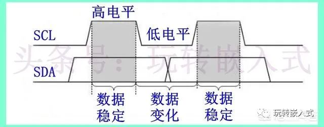
From the timing diagram, it can be seen that during the high level of SCL, the SDA data must not change. If the SDA data needs to be changed, it must be done during the low level of SCL. This is the meaning of this timing diagram. The microcontroller must follow this rule during programming.
The timing diagram is the basis for programming. When writing code, it is essential to strictly follow the timing diagram in the chip manual; otherwise, communication will fail. Therefore, it is important to review the timing diagrams and write code frequently.