
Click the blue text to follow us
“IEEE 1801, better known in the industry as the UPF standard, is a methodology for describing power intent, designing, and verifying power management architectures. Since its introduction, this standard has undergone four major updates, and compatibility issues between different versions have made it one of the hardest standards to support in the EDA field.“Ten years ago, two standards in the low-power domain finally merged after much anticipation from the industry. Before reaching this outcome, the industry experienced a phase where giants aligned themselves and operated independently, resulting in a confusing user experience. This standard is the current IEEE 1801 standard, now referred to as the low-power standard format (UPF).Before this standard was released, power consumption had already become one of the most troublesome issues for the entire industry, being a focal topic at international conferences for many consecutive years. At that time, processes continued to evolve according to Moore’s Law, and power consumption could still be improved. Although transistors shrank, the power consumption per unit area increased instead of decreased. Some even predicted that if no corresponding improvements were made to power consumption, the energy density of chip power consumption would catch up with that of rocket engine nozzles. Gradually, industry companies no longer hoped for miracles in the process, so they had to focus on design-related power reduction, which includes methods such as multi-voltage, power shutdown, and voltage islands. However, this resulted in the entire design process becoming fragmented, with each tool in the process having different file formats, making automation extremely difficult.Thus, users urgently needed a unified standard, and a tool capable of describing power intent became a market demand. Mika Naula, Nokia’s global IC tool manager, stated at that time that his requirements for power consumption standards were MISS (make it simple, silly) and KISS (keep it simple, stupid). He hoped for a standard that was usable, maintainable, and supported verification, which would help interoperability between tools.Against this backdrop, the industry’s first low-power standard, CPF (Common Power Format), was released in 2007.With CPF, designers could finally define their power consumption strategies and frameworks. Because it is a standard specification format, the power intent defined by engineers can be applied throughout the chip design and development process with just one definition. This greatly simplified the process, achieving a truly efficient effect.This tool, which should have brought more convenience to the entire industry, became a battleground for EDA giants, and the corresponding UPF standard was also developed. These two standards have different semantics; at that time, users evaluated CPF and UPF as being the same in terms of power intent, but in detail, they went their separate ways, and the call for the two standards to merge grew louder.Evolution of IEEE 1801
March 2007
The Silicon Integration Initiative (Si2) organization released CPF 1.0, which consists of 42 commands that can describe low-power intent. This standard not only significantly reduces chip power consumption but also enables efficient communication and collaboration across teams based on CPF’s full-process design. In the same year, Accellera passed the UPF 1.0 draft, which consists of 32 commands.
2008
Si2 released CPF 1.1. Since Accellera contributed UPF to IEEE, IEEE released the IEEE 1801-2009 standard, also known as UPF 2.0, in the same year. This standard is backward compatible with UPF 1.0 while incorporating some concepts from CPF. The biggest difference from version 1.0 is the introduction of the concept of supply_set, which has six functions for more comprehensive checks.
2011
CPF 2.0 was released. The new version optimized the hierarchical process, enhanced verification simulation processes, and improved interoperability with IEEE 1801.
May 2011
A milestone event that facilitated the future merger of power formats was Si2’s announcement to open the low-power methodology (OpenLPM) to IEEE. The direct benefit of methodology integration is enhanced interoperability between different formats in mixed low-power format design processes. In the long run, the convergence of methodologies has also become a fast track for standard format integration, allowing the two standards to reach consensus more quickly.
2013
After Si2 contributed CPF 2.0 to IEEE, IEEE 1801-2013 (UPF 2.1) was released this year, which included 11 new UPF commands. This version symbolized the official merger of CPF and UPF. It made further improvements to previous commands, introduced power models and repeater strategies, as well as some commands defining power management units. UPF 2.1 contains a total of 86 commands: 46 for power intent, 6 for power management, and 34 for query commands.
2014
Shortly thereafter, the revised version of UPF 2.1 was released in 2014—IEEE 1801a-2014 (UPF 2.2). This amendment did not introduce new commands, nor did it deprecate or delete any commands. This version corrected errors in UPF 2.1 and clarified ambiguities and inconsistencies related to power states, power, priority rules, and the position of power management units.
2015
IEEE 1801-2015 (UPF 3.0) was finalized and approved. This standard introduced 11 new commands, consisting of a total of 62 commands: 51 for power intent, 6 for power management, and 5 for query commands. New content includes enhanced functionality for power states and state transitions, as well as support for continuous improvement of power intent at different stages of the IC design process. This version also introduced detailed information models as the foundation for enhancing UPF functionality and query capabilities. Additionally, it now supports component power modeling for system-level power analysis in virtual prototype applications.
2018
The latest IEEE 1801-2018 (UPF 3.1) was released to date. This version is an important milestone for IEEE 1801, adding multiple new features and clarifying existing functionalities while maintaining a certain degree of backward compatibility with previous versions.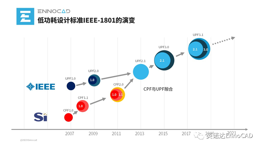 With the evolution of low-power design methodologies and an increasing number of users adopting UPF, the UPF standard will continue to iterate and upgrade, including but not limited to modifications of existing semantic incompleteness or ambiguities, and UPF will also meet users’ more diverse needs.UPF has gone through multiple generations of iterations to reach the present, yet users may not necessarily use the latest version due to usage habits. In some cases, when designs migrate to new standards, attribute specifications may cause errors, indicating potential issues in the design, as there may be conflicts between information from Liberty and UPF. Therefore, engineers also need to edit UPF files and ensure that the correct information set is specified in the power intent.Multiple Versions Cause AmbiguitiesAlthough IEEE 1801 is gradually becoming more refined, it has also caused some confusion for users, especially with semantic, syntax ambiguities, and even conflicts between various versions. Currently, commonly used EDA tools on the market often do not well support compatibility across various UPF versions, forcing chip engineers to accommodate EDA tools.Here are just a few examples to illustrate the differences between UPF versions.1. UPF Syntax Inconsistencies, but Semantics Are the Same1) Support for the Power State Table:UPF1.0Step 1: Define the power states of supply_ports
add_port_state vdd1 -state {s08 0.8} -state {off off}add_port_state vdd2 -state {s09 0.9} -state {off off}add_port_state vss -state {s0 0}Step 2:List the state relationships between supply_ports
create_pst PST1 -supplies {vdd1 vdd2 vss}add_pst_state M1 -pst PST1 -state {s08 s09 s0}add_pst_state M2 -pst PST1 -state {s08 off s0 }UPF2.0Step 1: Define the power states of supply_sets
create_supply_set SS1 -function {power vdd1} -function {ground vss}create_supply_set SS2 -function {power vdd2} -function {ground vss}add_power_state SS1 -state {on \
     -supply_expr { (power == {FULL_ON 0.8}) && (ground == {FULL_ON 0.0}) }add_power_state SS2 -state {on \
     -supply_expr { (power == {FULL_ON 0.9}) && (ground == {FULL_ON 0.0}) }
Step 2: List the state relationships between supply_sets
add_power_state pd1 -state {m1 -logic_expr { SS1==on && SS2==on }}2. Semantic Inconsistencies1)Different definitions of power domain boundariesIn UPF 1.0, the definition only includes the upper boundary, while in UPF 2.0 and above, it includes both the upper and lower boundaries. As shown in the figure, for the blue power domain, in UPF 1.0’s definition, the valid elements are P1 and P3. In UPF 2.0’s definition, the valid elements are P1, P2, and P3.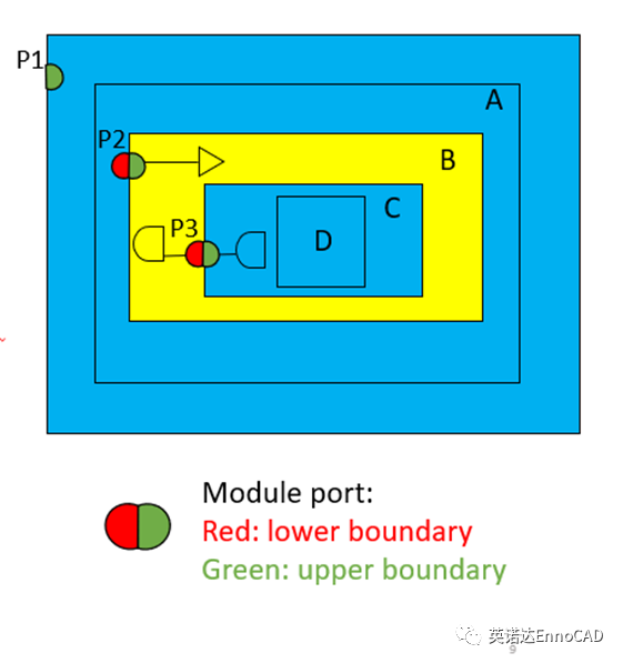 2)The default value of the option -diff_supply_only is differentIn the command for set_level_shifter, there is an option called -diff_supply_only. In UPF 2.1 and earlier versions: the default value is false, indicating that regardless of whether the source and sink power supplies are equivalent, whenever the set_level_shifter command is issued, a level shifter cell must be added to its elements. Later, the IEEE standards working group deemed this unreasonable because a level shifter cell is only required when the source and sink power supplies are not equivalent; thus, in UPF 3.0, the default value of -diff_supply_only was changed to true.Easily Achieve Low Power Design and Make Your Products CoolerThe market demand for low power is increasing, not only do portable devices require longer battery life, but non-portable devices also need to reduce cooling costs. Moreover, power consumption has become one of the significant bottlenecks restricting the development of high-performance chips in recent years. As society places more emphasis on environmental protection and sustainable development, more and more companies and organizations are taking action to promote the energy efficiency of electronic devices, which will also facilitate the adoption and promotion of the IEEE 1801 standard in chip design.Innodata, as a local EDA company, has been actively laying out in the low-power field since its establishment. Currently, the EnFortius® series low-power EDA tools have launched two low-power tools—LPC Low Power Design Verification Tool and GPA Gate-Level Power Analysis Tool. These two tools adopt a new product architecture and are the first EDA tools in the industry to build a core power intent data structure based on the UPF 3.1 version information model. This database is rich in functionality and can effectively access any power intent information described in UPF.Due to some historical reasons, before the launch of Innodata’s series of low-power EDA tools, there was no tool on the market that could simultaneously support CPF and early UPF versions. Additionally, due to the rapid pace of standard updates, many major companies still do not support some commands and semantics in the latest version. Innodata’s series of tools are compatible with the commands and semantics of older versions, ensuring maximum universality and flexibility to meet the practical needs of different customers.Innodata adheres to a customer-oriented philosophy aimed at helping customers maximize value, and will continue to delve into the low-power field, working with customers to overcome the challenges of low-power design and providing superior EDA solutions for China’s semiconductor industry.
References
EETimes , “Users speak out on IC power standards.” 2006.Sorin Dobre, Pete Hardee, Colin Holehouse, Minh Chau and Rolf Lagerquist, “Power Intent Formats: Light at the End of the Tunnel?” 2012.Qi Wang, “Opinion: What Comes After Power Intent Formats?” 2012.Qi Wang, “IEEE 1801-2013: A bold step towards power format convergence.” 2013.Lawrence Neukom, “UPF 3.0 is Now Official.” 2016.
About Innodata
Innodata (Chengdu) Electronic Technology Co., Ltd. is a local EDA company founded by industry-leading professionals. The company insists on a customer-oriented approach, helping clients maximize value and providing excellent EDA solutions for China’s semiconductor industry. Its independently developed EnFortius® series low-power EDA tools effectively assist IC design engineers in locating and analyzing low-power design-related issues. In addition, Innodata offers complete, customizable front-end/back-end design services, and its one-stop verification solutions can enhance chip design efficiency for manufacturers. The company’s long-term goal is to participate in the layout of a complete domestic EDA toolchain through the research and development of EDA tools and cloud practices, exploring paths and models suitable for China’s industrial software cloud applications, and empowering the high-quality development of the semiconductor industry.
Recommended Reading
Innodata Releases More Low-Power EDA Tools, Continuing Efforts in This Field
04-25

Innodata Wins 2023 Technical Breakthrough EDA Company Award
03-31

The “Push-Back Feeling” of System Verification Is More Than Just Speeding Up; EnCitius SVS Provides Complete Solutions for System Verification
03-29