There are many methods for low power design, but the most mature ones currently are gated power supply, multi-threshold voltage, and clock gating. Gated power supply technology involves adding a PMOS transistor between the pull-up network made of PMOS and VDD in some static CMOS circuits, or adding an NMOS transistor between the pull-down network made of NMOS and VSS, or both. When the circuit enters a sleep state, the power supply to that part of the circuit is directly cut off, thereby saving static power consumption. Multi-threshold voltage technology uses a cell library with multiple threshold voltages in the design. Using devices with a high threshold voltage can effectively reduce the system’s leakage current, thus reducing the system’s leakage power; however, their response speed is relatively slow. Devices with a low threshold voltage respond very quickly but have a correspondingly high leakage current, resulting in significant leakage power. For processes with very small feature sizes, leakage power accounts for a very large portion, which is why foundries prepare multi-threshold voltage cell libraries for some small feature size processes. For example, SMIC’s 90nm and 40nm standard cell libraries offer three types of devices with different threshold voltages, while the SMIC-28nm standard cell library provides as many as five types of core devices with different thresholds.
It can be seen that as the process enters the ultra-deep submicron stage, leakage power will become a very important factor limiting power consumption, and multi-threshold voltage technology is also a very important means of reducing power consumption. This design plans to use the SMIC-0.18μm process. Since the feature size of this process is not very small, the percentage of leakage power in the total power consumption is not very high, so this technology is not adopted in the design.
Clock Gating (CG) Technology
The principle of clock gating technology: Typically, not all logic circuits in digital circuits are always in a working state; some circuits are often in a waiting state, where the presence or absence of the clock signal does not affect the output results of the logic circuit. However, the introduction of the clock signal can cause unnecessary power waste. At this time, the clock signal for these circuits can be turned off to avoid power waste.
For example, we often see designs in Verilog HDL code as shown below, or these descriptions may be used in the design:
input [n:0] D;
input CLK, EN;
output [n:0] Q;
always@ (posedge CLK)
begin
if (EN)
Q <= D;
end
After synthesis with general synthesis tools, this design forms the circuit structure shown in diagram (a), which consists of a multiplexer and a register bank. If CG technology is used (taking latch-based CG technology as an example), it will form the circuit structure shown in diagram (b), which consists of a register bank and a clock gating cell (CGCell).
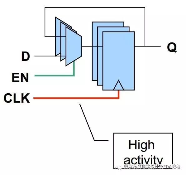
(a) Circuit structure synthesized without clock gating technology
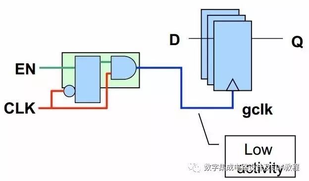
(b) Circuit structure synthesized with latch-based clock gating cell
Based on the comparison of the above circuit structures, it is easy to conclude that clock gating technology has the following advantages:
1. Reduces dynamic power consumption. CG technology controls the introduction of clock signals by adding a CG Cell to the clock input of the register bank. When EN=1, the clock signal can normally pass through the CG Cell to the clock input of the register bank, without affecting circuit functionality. When EN=0, the CGCell can block the clock input signal of the register bank, reducing switching activity and thus reducing switching power;
2. Can save area to some extent. As shown in the figure, one CGCell replaces multiple multiplexers. Therefore, under suitable conditions, CG Cell can also reduce system area;
3. Easy to implement. To apply CG technology in digital ICs, it does not require modifying RTL code; it only needs to set the CGCell and insert it automatically using commands. This technology is also independent of the process, making it easy to implement.