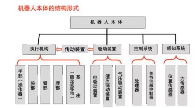
The pace of development in China’s manufacturing industry is accelerating, and the number of industrial robots used in Chinese factories is increasing. To become a technical talent in industrial robotics, one must understand the internal structure of industrial robots. Below, we will introduce the structure of general industrial robots.
1. Robot Drive System
Concept: To make the robot operate, it is necessary to install drive devices for each joint, i.e., each degree of freedom. Function: Provides the original power for the movements of various parts and joints of the robot.
Drive systems can be hydraulic, pneumatic, electric, or a combination of these; they can be direct drive or indirect drive through mechanisms such as synchronous belts, chains, gear systems, or harmonic gears.
1. Electric Drive Device
The energy source for electric drive devices is simple, with a wide range of speed variations, high efficiency, and both speed and position accuracy. However, they are often linked with reduction devices, making direct drive difficult.
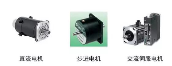
Electric drive devices can be divided into DC, AC servo motor drives, and stepper motor drives. DC servo motors are prone to brush wear and can produce sparks. Brushless DC motors are becoming increasingly popular. Stepper motor drives are mostly open-loop controlled, simple to control but not powerful, commonly used in low-precision, low-power robotic systems.
Before powering up the electric drive, the following checks should be made:
1) Is the power supply voltage appropriate (overvoltage may damage the drive module)? Ensure that the +/- polarity for DC input is not reversed, and that the motor model or current setting on the drive controller is appropriate (not too high at the beginning);
2) Ensure control signal wires are securely connected; in industrial environments, consider shielding (e.g., using twisted pairs);
3) Do not connect all required wires at the start; only connect the basic system and gradually connect more after ensuring it runs well;
4) Be clear about grounding methods; it may be preferable to leave it floating;
5) Closely observe the motor’s status during the first half hour of operation, checking for normal movement, sounds, and temperature rise; stop immediately to adjust if issues are found.
2. Hydraulic Drive
Accomplished through high-precision cylinders and pistons, linear motion is achieved by the relative motion between the cylinder and piston rod.
Advantages: High power, can eliminate the need for reduction devices by connecting directly to the driven rods, compact structure, good rigidity, fast response, and high precision in servo drive.
Disadvantages: Requires a hydraulic source, prone to liquid leaks, not suitable for high or low-temperature environments; thus, hydraulic drive is mostly used in very high-power robotic systems.
Choose suitable hydraulic oil. Prevent solid impurities from entering the hydraulic system, and prevent air and water intrusion. Mechanical operations should be smooth and gentle to avoid shock loads that can lead to frequent mechanical failures and significantly shorten lifespan. Pay attention to cavitation and overflow noise. Always monitor the sounds of the hydraulic pump and overflow valve during operation; if the hydraulic pump produces “cavitation” noise that doesn’t dissipate after venting, investigate and resolve the issue before use. Maintain suitable oil temperatures, generally keeping the hydraulic system’s working temperature between 30-80°C.
3. Pneumatic Drive
Pneumatic drive features a simple structure, cleanliness, and quick action with buffering effects. However, compared to hydraulic drive systems, it has lower power, poorer rigidity, higher noise, and speed control is difficult, so it is often used in low-precision position control robots.
(1) It features fast speed, simple system structure, easy maintenance, and low cost, suitable for medium and small load robots. However, due to the difficulty in achieving servo control, it is mostly used in program-controlled robots, such as in loading and unloading and stamping robots.
(2) It is mostly used for two-position or limited point control in medium and small robots.
(3) Currently, most control devices use programmable controllers (PLC). In flammable and explosive environments, pneumatic logic elements can be used to form control devices.
2. Linear Transmission Mechanisms
The transmission device is the key part connecting the power source and the moving link. Common transmission mechanisms based on joint forms include linear and rotary transmission mechanisms.
Linear transmission methods can be used for the X, Y, and Z-axis drives of Cartesian coordinate robots, radial drives of cylindrical coordinate structures, and vertical lift drives, as well as radial telescopic drives of spherical coordinate structures.
Linear motion can convert rotational motion into linear motion through components such as gear racks, screw nuts, or can be driven directly by linear motors or the pistons of cylinders or hydraulic cylinders.
1. Gear Rack Device
Typically, the rack is fixed. The rotational motion of the gear is converted into the linear motion of the support plate.
Advantages: Simple structure.
Disadvantages: Large backlash.
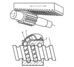
2. Ball Screw
In the screw and nut’s helical grooves, balls are embedded and guided to circulate continuously through the guiding grooves in the nut.
Advantages: Low friction, high transmission efficiency, no crawling, and high precision.
Disadvantages: High manufacturing cost and complex structure.
Self-locking issue: Theoretically, ball screw pairs can self-lock, but in practical applications, this self-locking is not used mainly due to poor reliability or high processing costs; since the diameter to lead ratio is very large, an additional set of worm gear or similar self-locking devices is generally added.
3. Rotary Transmission Mechanisms
The purpose of using rotary transmission mechanisms is to convert the high speed output from the motor’s drive source into a lower speed and obtain a larger torque. Common rotary transmission mechanisms used in robots include gear chains, synchronous belts, and harmonic gears.
1. Gear Chain
(1) Speed relationship
(2) Torque relationship
2. Synchronous Belt
The synchronous belt has many shaped teeth and meshes with a similarly shaped toothed synchronous pulley. During operation, it acts like a flexible gear.
Advantages: No slipping, good flexibility, low cost, and high repeat positioning accuracy.
Disadvantages: Exhibits some elastic deformation.
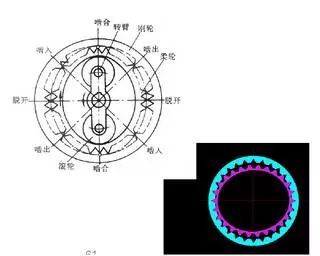
3. Harmonic Gear
The harmonic gear consists of three main parts: a rigid gear, a harmonic generator, and a flexible gear, with the rigid gear usually fixed and the harmonic generator driving the flexible gear to rotate.
Main characteristics:
(1) High transmission ratio, single-stage 50-300.
(2) Smooth transmission with high load capacity.
(3) High transmission efficiency, reaching 70%-90%.
(4) High transmission accuracy, 3-4 times higher than ordinary gear transmission.
(5) Low backlash, can be less than 3’.
(6) Cannot obtain intermediate output, with lower stiffness of the flexible gear.
Harmonic transmission devices have been widely used in countries with advanced robotics technology. In Japan, for instance, 60% of robot drive devices utilize harmonic transmission.
The robots sent to the moon by the United States used harmonic transmission devices in all their joint parts, with one upper arm using 30 harmonic transmission mechanisms.
The mobile robot “Lunokhod” sent to the moon by the former Soviet Union had its eight paired wheels driven by closed harmonic transmission mechanisms. Robots such as the ROHREN and GEROT R30 developed by Volkswagen and the VERTICAL 80 developed by Renault in France also adopted harmonic transmission mechanisms.
4. Robot Sensor Systems
1. The sensory system consists of internal sensor modules and external sensor modules to obtain meaningful information about the internal and external environmental states.
2. The use of intelligent sensors enhances the robot’s mobility, adaptability, and intelligence level.
3. The use of intelligent sensors enhances the robot’s mobility, adaptability, and intelligence level.
4. For certain specific information, sensors can be more effective than human sensory systems.
5. Robot Position Detection
Rotary optical encoders are the most commonly used position feedback devices. Photoelectric detectors convert light pulses into binary waveforms. The angle of the shaft is calculated based on the number of pulses, and the direction of rotation is determined by the relative phase of two square wave signals.
Inductive synchronizers output two analog signals—sine and cosine signals of the shaft’s rotation angle. The shaft’s rotation angle is calculated from the relative amplitudes of these two signals. Inductive synchronizers are generally more reliable than encoders, but their resolution is lower.
Potentiometers are the most direct form of position detection. They are connected in a bridge circuit and can produce a voltage signal proportional to the shaft’s rotation angle. However, they have low resolution, poor linearity, and are sensitive to noise.
Speedometers can output an analog signal proportional to the shaft’s speed. If such speed sensors are not available, speed feedback signals can be obtained by differentiating the detected position concerning time.
6. Robot Force Detection
Force sensors are usually installed in three positions on the robotic arm:
1. Installed on the joint driver. They can measure the torque or force output of the driver/reducer itself but cannot effectively detect the contact force between the end effector and the environment.
2. Installed between the end effector and the terminal joint of the robotic arm, known as wrist force sensors. They can typically measure three to six force/torque components applied to the end effector.
3. Installed on the “fingertips” of the end effector. These force-sensitive fingers typically have strain gauges built in to measure one to four force components applied to the fingertips.
7. Robot-Environment Interaction Systems
1. The robot-environment interaction system is a system that enables industrial robots to connect and coordinate with devices in the external environment.
2. Industrial robots integrate with external devices into a functional unit, such as processing and manufacturing units, welding units, assembly units, etc. It can also integrate multiple robots, machine tools, or devices, as well as multiple part storage devices.
3. It can also integrate multiple robots, machine tools, or devices, as well as multiple part storage devices into a functional unit to execute complex tasks.
8. Human-Machine Interaction Systems
The human-machine interaction system is a device that allows operators to participate in robot control and communicate with the robot. This system can be summarized into two main categories: command input devices and information display devices.
☞ Source: Industrial Robots
☞ Advertising Cooperation: Sun Ha 13811718902
Statement: If there are any copyright issues regarding the videos, images, or text used in this article, please notify us immediately. We will confirm copyright based on the materials you provide and pay remuneration according to national standards or delete the content immediately!
Statement: If there are any copyright issues regarding the videos, images, or text used in this article, please notify us immediately. We will confirm copyright based on the materials you provide and pay remuneration according to national standards or delete the content immediately!