

Article Directory
1. Setup Stage: Transaction
1.1. Token Packet
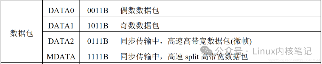
1.2. DATA0 Data Packet
2. Explanation of Optional Data Stage Packets
3. Explanation of Status Stage Packets
Control transfer consists of three stages: setup stage, optional data stage, and status stage. The setup stage consists of one SETUP transaction, while the data stage consists of <span>0</span> or more <span>IN/OUT</span> transactions, and the status stage consists of one <span>IN/OUT</span> transaction. Each stage has a different packet structure, as visually represented in the diagram below.
1. Setup Stage: Transaction
<span>USB</span> defines the basic unit of data transmission on the bus as a packet, but packets cannot be used to transmit data arbitrarily. These different packets must be organized into transactions (<span>Transaction</span>) according to certain relationships to transmit data. A transaction typically consists of two or three packets: a token packet, a data packet, and a handshake packet.
-
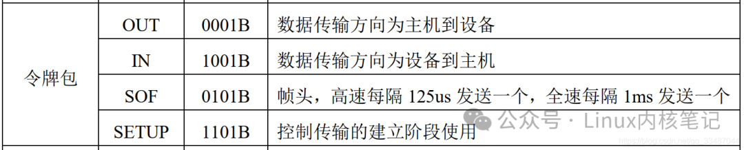
The token packet is used to initiate a transaction and is always sent by the host. -
The data packet transmits data and can go from the host to the device or from the device to the host, with the direction determined by the token packet. -
The sender of the handshake packet is usually the data receiver, who sends the handshake packet when the data is received correctly. The device can also use <span>NAK</span>handshake to indicate that the data is not yet ready.
The setup stage consists of one setup transaction, and the <span>SETUP</span> transaction is composed of a <span>SETUP</span> token packet, a <span>DATA0</span> data packet, and an <span>ACK</span> handshake packet, as shown in the diagram below.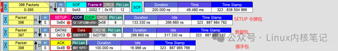
1.1. Token Packet
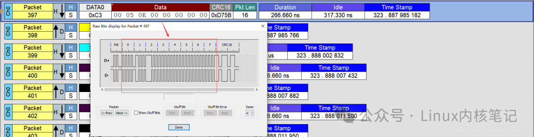
From the above diagram, we can see that the <span>SETUP PID</span> is <span>1101B</span>, so the two’s complement check bit is <span>0010</span>. The transmission on the link is low first and then high, which is <span>1011_0100 (0xB4)</span>. The following diagram shows the link waveform of the <span>SETUP</span> packet.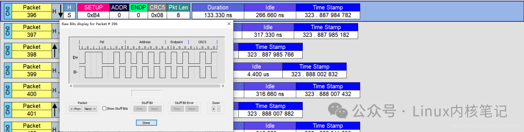
1.2. DATA0 Data Packet
Control transfer consists of three stages: setup stage, optional data stage, and status stage. The setup stage consists of one <span>SETUP</span> transaction, the data stage consists of <span>0</span> or more <span>IN/OUT</span> transactions, and the status stage consists of one <span>IN/OUT</span> transaction. Each stage has a different packet structure, as visually represented in the diagram below.
2. Explanation of Optional Data Stage Packets
1. If the first stage specifies the data transmission direction as device to host: If the first stage specifies read (data transmission direction is device to host), then the data stage will consist of multiple consecutive <span>IN</span> transactions, with the transaction and packet protocol structure shown in the diagram below: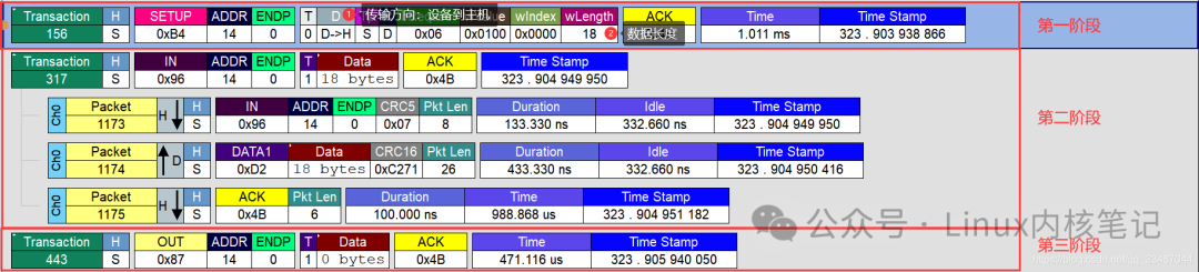
2. If the first stage specifies the data transmission direction as host to device (data length greater than <span>0</span>): If the first stage specifies write (data transmission direction is host to device), then the data stage will consist of multiple consecutive <span>OUT</span> transactions, with the transaction and packet protocol structure shown in the diagram below.
3. If the first stage specifies the data transmission direction as host to device (data length is <span>0</span>):
3. Explanation of Status Stage Packets
The status stage consists of one <span>OUT/IN</span> transaction:
1. If the second stage specifies the data transmission direction as device to host: If the second stage specifies the data transmission direction as device to host, then after the host receives the data, the host requests an <span>OUT</span> transaction to inform the device of the data reception status.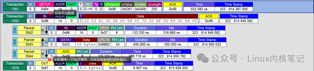
2. If the second stage specifies the data transmission direction as host to device (data length greater than <span>0</span>): If the second stage specifies the data transmission direction as host to device, then after the host finishes sending the data, the host requests an <span>IN</span> transaction to check the device’s data reception status.
3. If the second stage specifies the data transmission direction as host to device (data length is <span>0</span>): If the second stage specifies the data transmission direction as host to device, and the requested data transmission length is 0, then after the host sends the token packet, the host requests an <span>IN</span> transaction to check the device’s data reception status.