
I mentioned in a previous article about the information on outputting waveforms using the MDK built-in logic analyzer. I found that some people are interested in using the MDK built-in logic analyzer to implement waveform output. Below, I will use the STM32F334 DAC module to output an arbitrary waveform and display the waveform using the ARM MDK IDE built-in logic analyzer. I will try to describe the entire process in detail.
I used the TIM6 update event to trigger the DMA, allowing the DMA to transfer the memory data I prepared in advance to the DAC channel 1 data holding register【DAC1->DHR12R1】. Then, in the TIM6 interrupt, I read the content of the DAC data output register【DOR】into a global variable【DAC_Out】, which will be used as an analog quantity in the logic analyzer and output this signal.
At the same time, I connected the DAC output to channel 1 of the ADC1 module as its input, performing AD conversion on the signal coming from the DAC, and storing the ADC results in another memory space through DMA. I utilized the TIM3 update event to periodically trigger the ADC, and in the TIM3 update interrupt, I assigned the latest ADC data to another global variable【ADC_Res】, which will also be output as another analog quantity in the MDK_IDE logic analyzer.
1. Let’s start using STM32CubeMx for graphical configuration
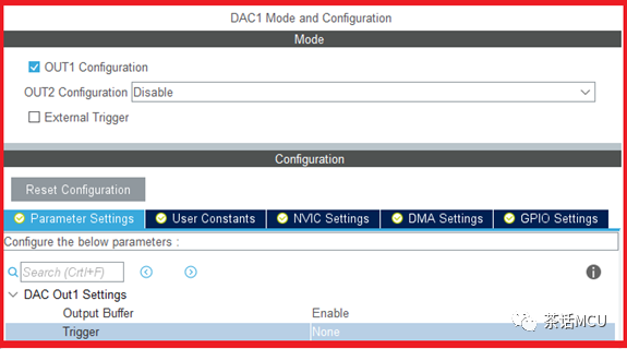
1. The configuration of the DAC is as follows. The configuration is straightforward, just enabling the output of DAC channel 1. As for the output buffer, it can be configured based on specific circumstances; here it is enabled.
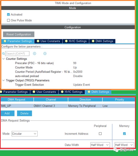
2. Configure TIM6. The main purpose is to use its update event to trigger DMA, transferring data from memory to the DAC’s register.
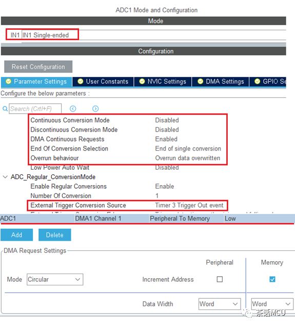
3. The configuration of the ADC. Here, only one channel is enabled, with the TIM3 update event serving as the ADC start trigger event. The ADC conversion complete event triggers DMA transfer to take the ADC results.
4. The configuration of TIM3. Its configuration is also quite simple, setting appropriate base parameters and enabling the update interrupt.
The peripheral configuration mainly consists of the above; the configurations related to DMA and RCC will not be illustrated further.
2. After the configuration is complete, generate the initialization files, and then add user code.
1. Data preparation. Since we need to use the DAC to output an arbitrary waveform, we can first simulate the output waveform using other tools. The easiest way is to use the mathematical function feature of EXCEL to simulate the related waveform. Here, several trigonometric functions are combined to form a new function. Based on this function, a data sequence is generated for DAC output.

2. Add user code.
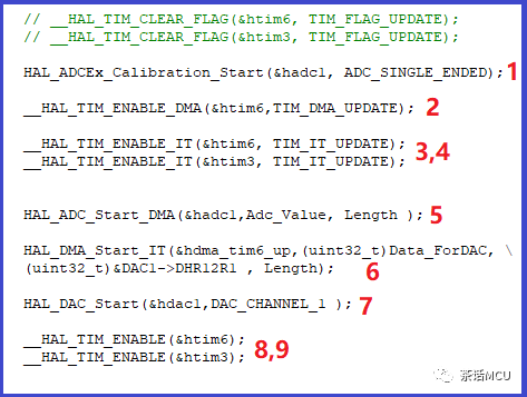
The user code to be added is the following few lines, which are quite clear and need no further explanation. Among them, length is a macro-defined constant representing the number of data points. The following code is based on the STM32Cube library.
3. Interrupt function handling.
In the TIM6 update interrupt, add the following code to obtain the DAC output data in real-time.
DAC_Out= DAC1->DOR1;
In the TIM3 update interrupt, add the following code to read the ADC results in real-time.
ADC_Res=(uint16_t)Adc_Value[Length-DMA1_Channel1->CNDTR];
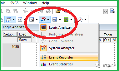
3. Configuration for the MDK logic analyzer

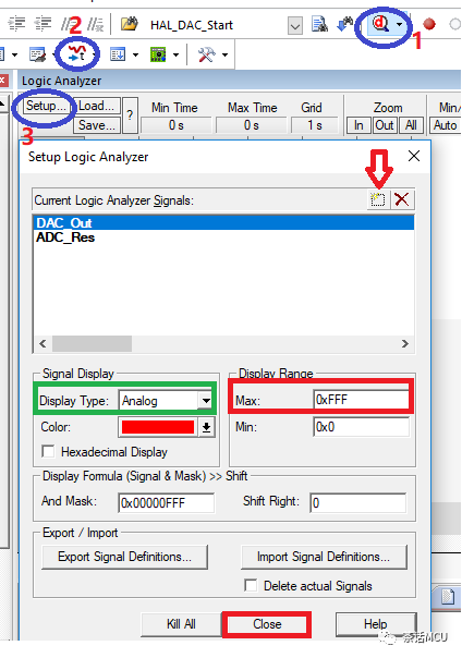
Here, please note that the Core_clock must be consistent with the system clock configured for your chip. Additionally, Trace Enable must be checked. After entering debug mode, continue configuring the logic analyzer. The red numbers1/2/3 in the image indicate the order of operations.

Click the arrow to add the global variables we prepared earlier and configure them appropriately. The two variables added here are both analog quantities, so the display type is selected as Analog and the display color is based on personal preference.Note that there are issues with setting the minimum and maximum values for analog quantities; too large or too small is not suitable, which is easy to understand. The configuration in the masked area is specified according to the data range to be displayed. The experimental data will not exceed 0xfff so it is configured as shown in the image.
4. View results
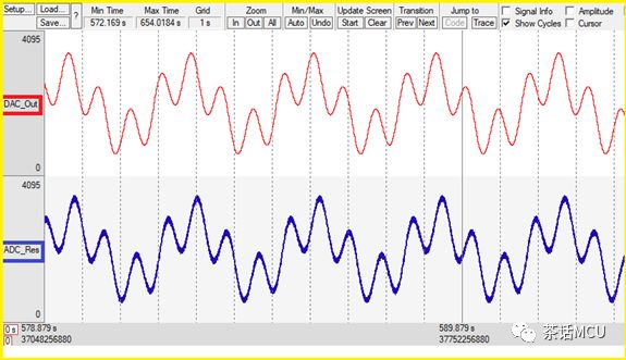
The first screenshot below shows the two waveforms output by the MDK built-in logic analyzer. The red curve is the waveform output from the DAC and the blue curve is the real-time result waveform obtained after ADC conversion.
It is not difficult to see that the two waveforms are consistent periodic outputs, but there is a difference between the ADC output and the DAC output because the ADC result is obtained after sampling and converting the DAC output, so there is a timing lag. The second image is a screenshot after adjusting the time observation width.

Okay, this concludes the introduction on using the MDK built-in logic analyzer for arbitrary waveform output, and I have also briefly introduced some configurations and applications of STM32 ADC/DAC.
As for this tool built into MDK, if you know how to use it, it can sometimes make our debugging easier. It is not difficult to use, so if you are interested, feel free to give it a try.
================================
Previous topics link [click to read]:
1. Several basic issues of STM32H7 series dual-core products
2. Introduction to several programming methods for STM32 chips
3. Two misunderstandings about debugging STM32 in the KEIL MDK environment
4. Application example of STM32 ADC interrupt conversion mode
5. A case analysis of a low-power application