A Dual-Shoulder Backpack
How Difficult Is It?
Give It a Try!
→_→

Circuits synthesized from FPGA are located inside the chip, making it nearly impossible to measure signals using oscilloscopes or logic analyzers. Therefore, manufacturers like Xilinx have invented built-in logic analyzers. In Vivado, this is called ILA (Integrated Logic Analyzer), whereas it was known as ChipScope in ISE. The basic principle is to use internal gate circuits of the FPGA to construct a logic analyzer, synthesizing an ILA core that extends many probes to detect signal lines.
Below, I will explain the online debugging process step by step, focusing mainly on the correct use of the clock domain within ILA.
Part One: Adding Measured Signal Lines
There are usually two ways:
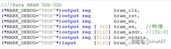
1. Add this line in the code (*MARK_DEBUG=”TRUE”*). Whether it is a reg or wire type, interface signal, or internal variable, they can all be added.
2. Directly add Netlist during the Setup Debug process.
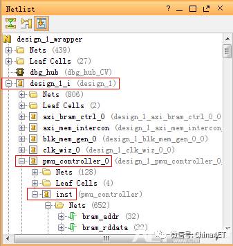
I usually add DEBUG tags to commonly used signals, manually add nets for temporary measurements, and add or delete as needed.
Part Two: Generating the ILA Module
-
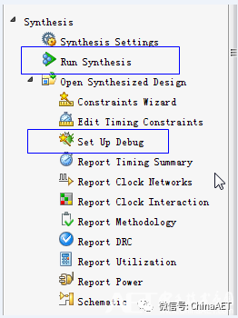
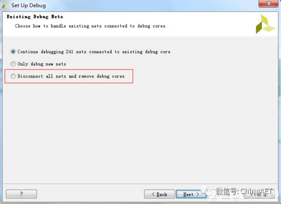
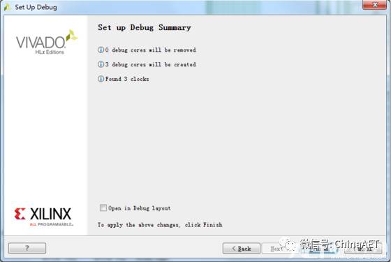
After synthesis is complete, Open Synth Design, and click on Set Up Debug.
-
Select one as needed.
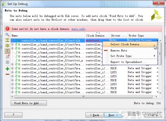
-
After entering, you can add/delete the nets to be measured. If prompted that there is no reference clock, right-click to select a suitable one.
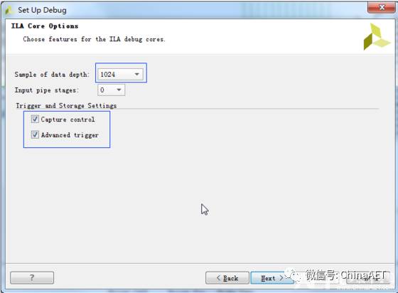
-
Select the FIFO depth. This depth can be set quite large; each measured signal will have such a large FIFO, so the logic analyzer occupies a lot of BRAM resources! Reasonably setting trigger conditions means that you don’t need to select too large a FIFO.
-
Here, I will jump back to the previous step to discuss the importance of selecting the clock domain in conjunction with the FIFO mentioned above.
The selection of the clock domain affects two major aspects: the number of ILA cores generated and how much time can be detected.
1) Selecting three clocks will definitely generate three ILA cores because the clk given to the D flip-flops is different;
2) The reference clock of the FIFO directly determines how long the FIFO will be filled;
For example, in this design, there are three clocks coming in: 50MHz, 20MHz, and 8MHz converted to 400kHz for IIC use. If the reference for IIC is 50MHz, then the scl and sda FIFOs will be filled instantly, and after triggering, the FIFO’s task is completed, but we won’t see a single signal transition. If the reference is 400kHz, then we can capture everything from the start condition to the 8-bit data to the stop condition.
The FIFO stores data based on the reference signal clock; it will store 1 bit of data only when there is one clk.
Selecting the appropriate clock domain is crucial as it ultimately affects resource utilization. The number of ILA cores, the number of FIFOs (it often happens that we need to capture 500 or even 1000 signals. Why so many! For example, you have a 32-bit address, a 32-bit bus, separate read and write, and several others, which gradually accumulate. The FPGA’s functionality is based on the principle of using parallel buses to increase speed).
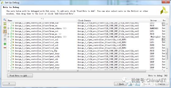
For example, in the settings below, it will definitely generate three ILA cores, displayed in three waveform interfaces. In fact, if resources are sufficient, it is recommended to separate according to major functions so that they can be displayed on different interfaces, each with its own trigger conditions.
Part Three: Signal Waveforms
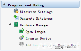
-
Connect to JTAG, open the target board, and then program the bit and ltx files.
-
Set the trigger conditions. This is similar to the usage with oscilloscopes, where you can use run or trig.
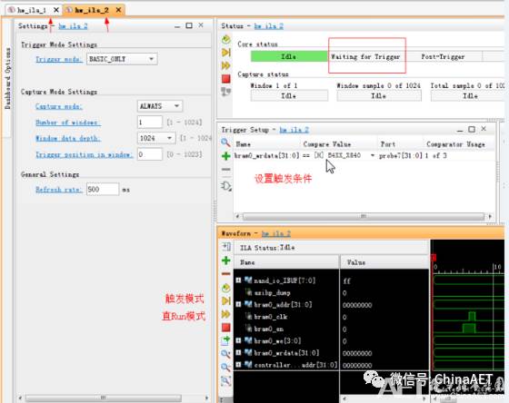
-
Right-click for many functions: short display names, set colors, base conversion, grouping, etc., which can be explored.
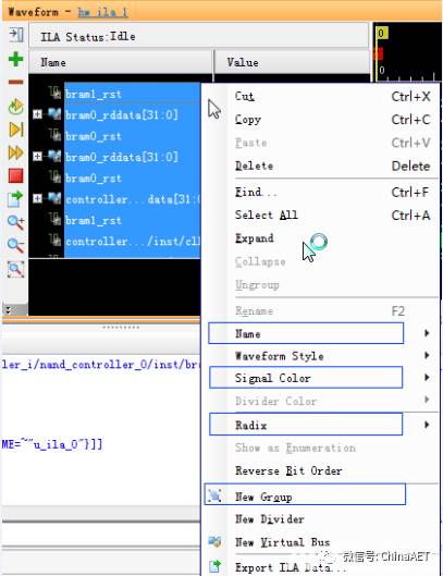
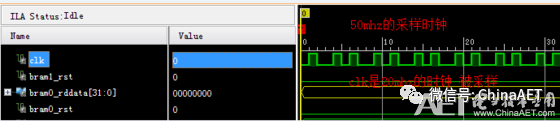
-
For example, the signal being measured is a 20MHz clk, but the displayed waveform is not a uniform square wave! Why? Because it was sampled with a 50MHz clock, which is why it looks like this, and there is no mistake. So, once again, the selection of the clock domain is very important.