Click the blue text to follow us
Follow and star our public account for exciting content delivered daily

Source: Online materials
Build a 100MHz Logic Analyzer in Minutes
Transform a Raspberry Pi Pico (or any RP2040 board) into a simple logic analyzer in just 5 minutes.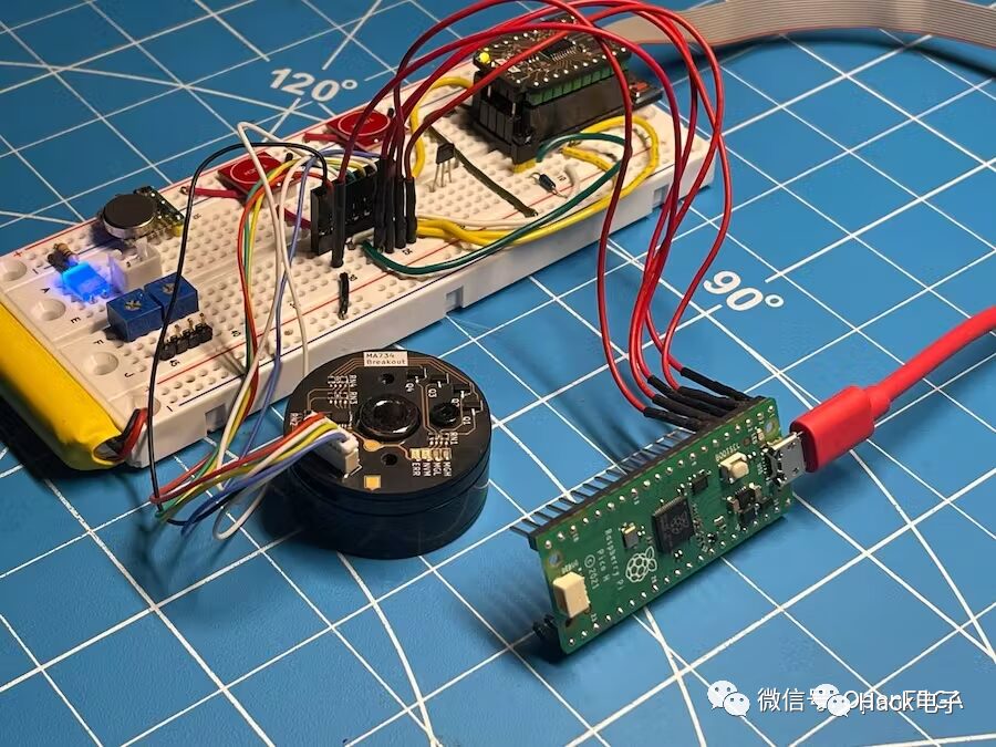
Introduction
A logic analyzer is an electronic instrument that captures and displays multiple signals from digital systems or circuits. It can convert the captured data into timing diagrams, protocol decoding, state machine tracking, and opcodes, or associate opcodes with source-level software. Logic analyzers are very useful when users need to examine the timing relationships between many signals in a digital system.
μLA is a SUMP/OLS compatible logic analyzer firmware suitable for RP2040-based boards.
Features
-
16 channels
-
100 MHz sampling rate (up to 250 MHz when properly optimized (overclocked)), capturing 1 sample per system clock cycle
-
200 KB memory
-
Fast triggering using PIO
Supported Hardware
-
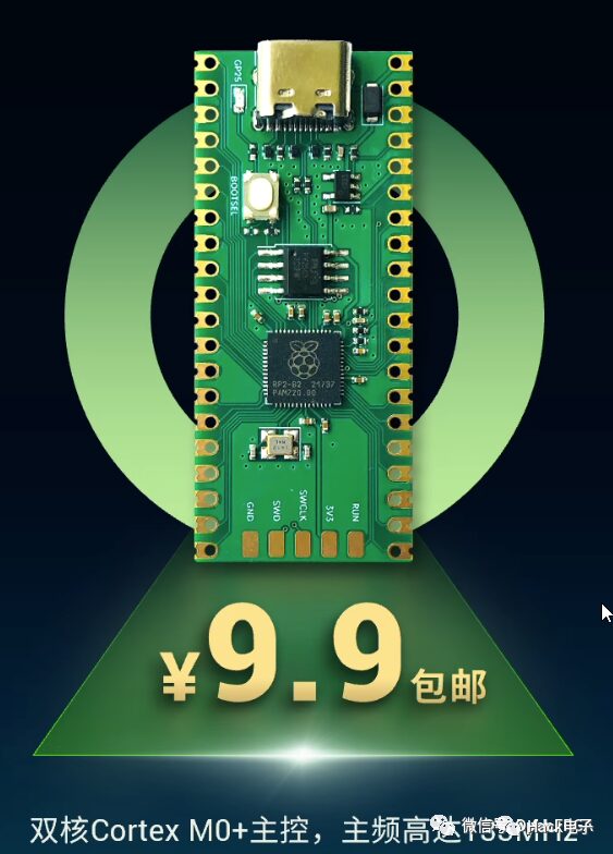
Raspberry Pi Pico
-
RP2040-zero
-
All RP2040-based boards (must have USB connection)
Installation
-
Download the latest µLA firmware from the link below
https://github.com/dotcypress/ula/releases
-
Hold down the BOOTSEL button while connecting the development board to the computer
-
Copy the downloaded firmware file to the RP2040
-
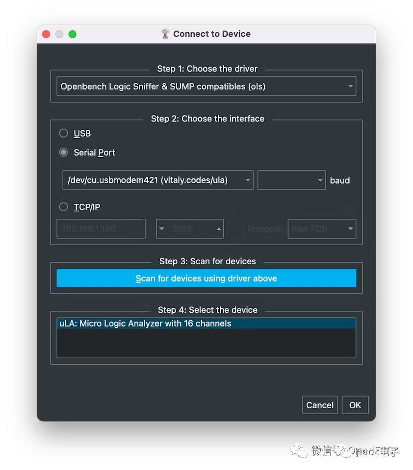
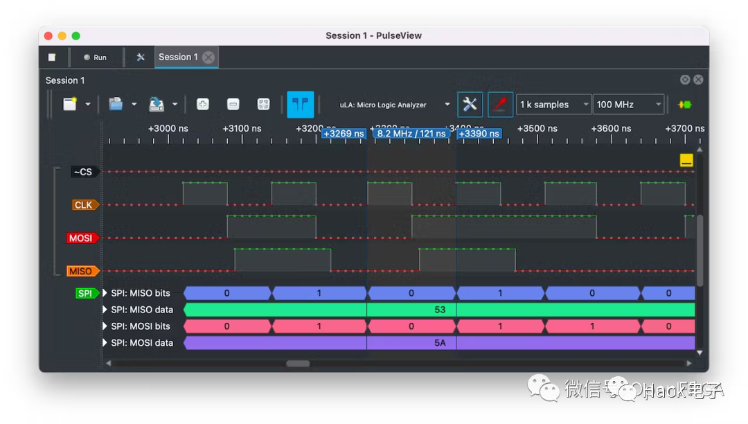
Use PulseView or sigrok-cli for host-side data collection and analysis
https://sigrok.org/wiki/PulseView
https://sigrok.org/wiki/Sigrok-cli
-
Enjoy
Code
https://github.com/dotcypress/ula
https://sigrok.org/wiki/PulseView
https://sigrok.org/wiki/Sigrok-cli

Want to learn about FPGA? Here are some example shares, ZYNQ design. Follow our public account to explore.