For hardware engineers, the first acquaintance with serial communication may be RS232 (“RS” stands for “Recommended Standard”, indicating a “recommended standard”. “232” is the identification number), which has been widely used for communication between microcontrollers and computers due to its simplicity and low cost (for example, using a USB to RS232 module to upload microcontroller data to a computer’s serial assistant), commonly referred to as COM1 and COM2. Today, we will introduce RS232 from a hardware perspective.
1. First, let’s clarify: What is RS232?
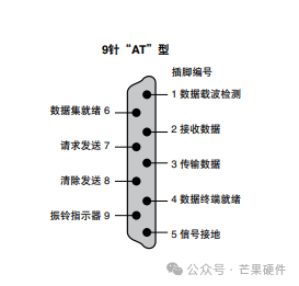
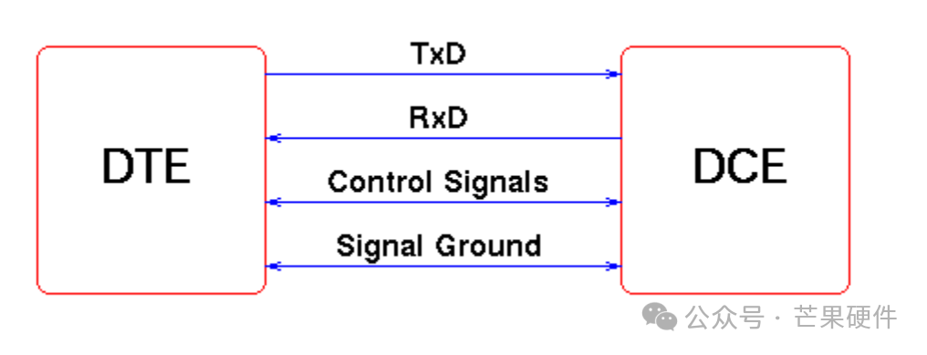
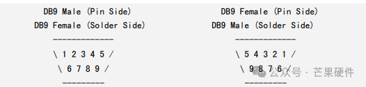
RS232 (Recommended Standard 232) is a standard for serial communication interfaces, essentially achieving asynchronous data transmission between devices through “a transmission line, a receiving line, and a ground line” — no clock signal synchronization is required, and data accuracy is ensured by “agreed communication parameters”. Its common male and female interface sequence and pin definitions are shown in the figure below:
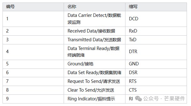
The most common RS232 interface is DB9 (9 pins), but in most communication scenarios, only 3 wires are needed, while the rest are flow control or spare pins. The specific definitions are as follows:
2 RX Receive data (device’s “input”) Must connect
3 TX Send data (device’s “output”) Must connect
5 GND Signal ground (reference benchmark) Must connect
7 RTS Request to send (hardware flow control) Optional
8 CTS Clear to send (hardware flow control) Optional
The core principle is:
Using single-ended signal transmission: using GND as a reference, the voltage changes of TX (transmitter) and RX (receiver) represent data (for example, +3~+15V represents logic “0”, -3~-15V represents logic “1”);
Synchronizing through “frame structure”: each data frame contains a start bit, data bits, parity bit, and stop bit. The receiver identifies the start of data through the start bit and disassembles the data according to the parameters.
2. RS232 Hardware Characteristics
1. Voltage:
The voltage logic of RS232 is completely different from the TTL (3.3V/5V) we are familiar with, which is the most common pitfall for beginners:
TTL logic: High level (3.3V/5V) = logic “1”, Low level (0V) = logic “0”;
RS232 logic: Positive voltage (+3~+15V) = logic “0”, Negative voltage (-3~-15V) = logic “1”;
If you directly connect the MCU’s TTL serial port to an RS232 device, the chip may burn out due to voltage mismatch, so a level conversion circuit must be added.
Moreover, RS232 is asynchronous communication, and both parties must agree on 4 parameters; otherwise, there will be “garbled characters” or “no response”:
2. Baud Rate:
Baud rate:Data transmission rate (e.g., 9600bps, 115200bps), with the most common being 9600bps (9600 bits per second);
Data bits: The number of valid bits in each data frame (usually selected as 8 bits, i.e., 1 byte);
Stop bits: The “end identifier” at the end of each data frame (usually selected as 1 bit);
Parity bit: Used to detect data errors (usually selected as “no parity”, i.e., N).
In daily use, we often configure as “9600bps, 8 data bits, 1 stop bit, no parity”, abbreviated as “9600 8N1”.
3. Key Considerations in Hardware Design:
1. Level conversion is essential: The MCU’s TTL serial port cannot be directly connected to RS232 devices, and chips like MAX232 or SP3232 must be used to convert TTL levels to RS232’s positive and negative voltages;
2. Wiring must not be reversed: The two communicating parties must be “cross-connected” —Device A’s TX connects to Device B’s RX, Device A’s RX connects to Device B’s TX, and GND must be common ground (otherwise, there will be no signal);
3. Distance must not exceed limits:For unshielded cables, the recommended transmission distance is <10 meters; if it exceeds, shielded cables must be used, and they should be kept away from power lines (to avoid electromagnetic interference causing garbled characters);
4. Parameters must be consistent:The baud rate, data bits, and other parameters of the computer’s serial assistant, MCU program, and peripherals must be exactly the same; otherwise, communication will fail (for example, if one side is 9600bps and the other is 115200bps, it will only display garbled characters).