

1. Working Principle of Sensors
A sensor is a device that converts non-electrical quantities into electrical quantities. The non-electrical quantities sensed typically include pressure, temperature, displacement, concentration, speed, pH, etc. The output is usually an electrical quantity, such as voltage, current, or charge. These output signals are very weak and usually need to be amplified before being sent to a control system to generate various control actions. The principle of sensors is illustrated in the figure.
2. Common Sensors
1. Photoresistor
(1) The resistance of a photoresistor changes when exposed to light, allowing it to convert light intensity into an electrical quantity of resistance.
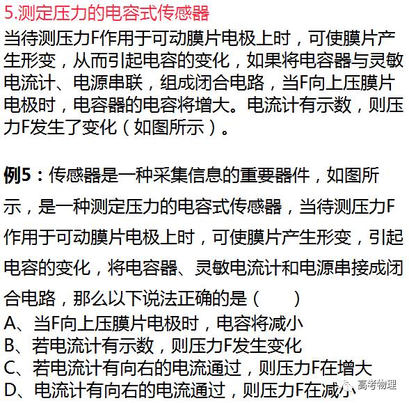
(2) The resistance of the photoresistor decreases as light intensity increases.
A photoresistor is generally made of semiconductor materials. When the semiconductor material is exposed to light or the temperature rises, more electrons gain energy to become free electrons, creating more holes, which significantly enhances conductivity.
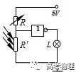
Example 1: The right figure shows a simple circuit diagram containing a logic circuit, where L is a small bulb. When light shines on the resistor, its resistance will become much smaller than R, thus the correct statement is ( )
A. This logic circuit is a NOT gate; when the resistor is illuminated, the bulb L does not light up.
B. This logic circuit is a NOT gate; when the resistor is illuminated, the bulb L lights up.
C. This logic circuit is an AND gate; when the resistor is illuminated, the bulb L does not light up.
D. This logic circuit is an OR gate; when the resistor is illuminated, the bulb L lights up.
Answer: B
2. Thermistor
A thermistor is made of semiconductor materials, and its resistance changes significantly with temperature, decreasing as temperature increases.
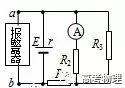
Example 2: The figure shows a partial circuit diagram of a fire alarm. R3 is a sensor made of semiconductor thermistor material. The display in the duty room is an ammeter in the circuit, and the alarm is connected between a and b. When a fire occurs at the location of the sensor R3, the changes in current I on the display and the voltage U across the alarm are ( )
A. I increases, U increases.
B. I increases, U decreases.
C. I decreases, U decreases.
D. I decreases, U increases.
Answer: C

3. Hall Effect Sensor
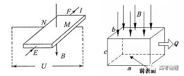
As shown in the figure, a conductor plate with thickness d is placed in a uniform magnetic field with magnetic induction B perpendicular to it. When a constant current I flows through the conductor plate, a potential difference appears on the left and right sides of the conductor plate, a phenomenon known as the Hall Effect. By placing four electrodes EFMN on this rectangular semiconductor, it becomes a Hall Effect sensor that can convert the magnetic induction strength into a voltage.
Example 3: To measure the wastewater discharge of a chemical plant, technicians installed a flow meter at the end of the drainage pipe as shown. The device is made of insulating material, with lengths a, b, c, and openings at both ends. A uniform magnetic field with magnetic induction B is applied perpendicular to the top and bottom surfaces. Metal plates are fixed as electrodes on the inner sides of the front and back. When wastewater flows from left to right through the device, the voltmeter will show the voltage U between the two electrodes. If Q represents the wastewater flow rate (volume of wastewater discharged per unit time), which of the following statements is correct? ( )
A. If there are more positive ions in the wastewater, the front surface will have a higher potential than the back surface.
B. The potential of the front surface is always lower than that of the back surface, regardless of which ions are more abundant.
C. The higher the ion concentration in the wastewater, the greater the reading on the voltmeter.
D. The wastewater flow rate Q is proportional to U and independent of a and b.
Answer: BD

4. Force Sensor
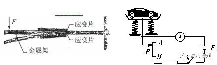
(1) Components of an electronic scale: consist of a metal frame and strain gauges.
(2) Working principle of the electronic scale: As shown in the figure, a beam element made of spring steel is fixed at one end. A strain gauge is attached to the upper and lower surfaces of the beam. When a force F is applied at the free end of the beam, it bends, stretching the upper surface and compressing the lower surface. The resistance of the strain gauge on the upper surface increases, while that on the lower surface decreases. The greater the force F, the greater the bending deformation, leading to a larger change in the resistance of the strain gauge. If the current through the strain gauge is kept constant, the voltage across the strain gauge on the upper surface increases, while the voltage across the strain gauge on the lower surface decreases. The sensor outputs the difference in these two voltages. The greater the external force, the greater the output voltage difference.
Example 4: The figure shows a schematic of a weighbridge used to measure the mass of a car. The mass of the car can be read from the ammeter’s reading, and the correct statement is ( )
A. The larger the reading on the ammeter, the greater the mass of the car being measured.
B. The larger the reading on the ammeter, the smaller the mass of the car being measured.
C. The maximum capacity of the weighbridge is determined only by the stiffness of the spring and is independent of other circuit parameters.
D. Replacing the ammeter in the figure with a voltmeter can also measure the mass of the car.
Answer: A

For more information on the college entrance examination and application details, please add the college entrance examination assistant.


College Entrance Examination Physics
Account ID: gkwl100
A summary of high school physics knowledge points and answering techniques, as well as practice questions and answer templates, everything you need is here!