
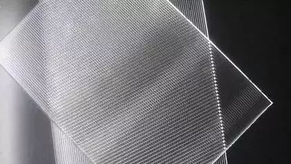
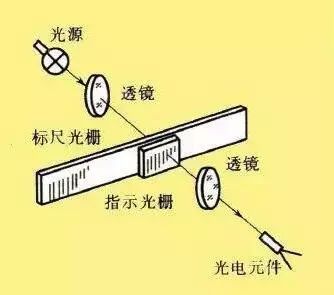
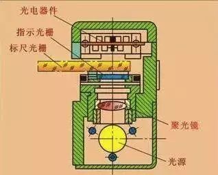
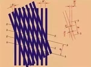
Grating Sensors
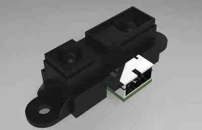
Infrared Sensors
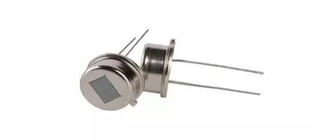
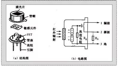
Pyroelectric Infrared Sensors
Fiber Optic Gyroscope Sensors
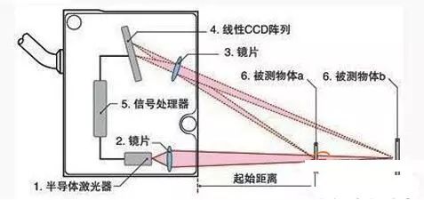
Laser Displacement Sensors
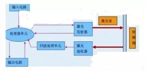
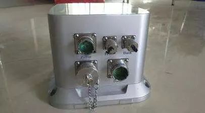
Laser Ranging Sensors
0.001m(3X10^8m/s)=3ps
Grating Sensors
Infrared Sensors
Pyroelectric Infrared Sensors
Fiber Optic Gyroscope Sensors
Laser Displacement Sensors
Laser Ranging Sensors
0.001m(3X10^8m/s)=3ps