Getting Started with Raspberry Pi 5 GPIO
GPIO, which stands for General Purpose Input/Output, is a critical interface for connecting external devices, transforming your Raspberry Pi into a multifunctional control center.
GPIO is also key for Internet of Things (IoT) development, as many devices require data interaction through GPIO interfaces.
The 40-pin header supports digital signal transmission and can connect buttons, LED lights, sensors, and even motors… Just imagine, with just a few lines of code, you can light up the night and start a small robotic arm. Isn’t that cool?
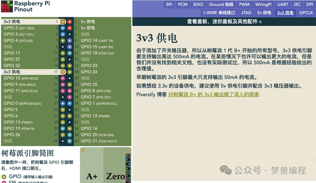
Generally, before development, we need to consult the GPIO pinout diagram.
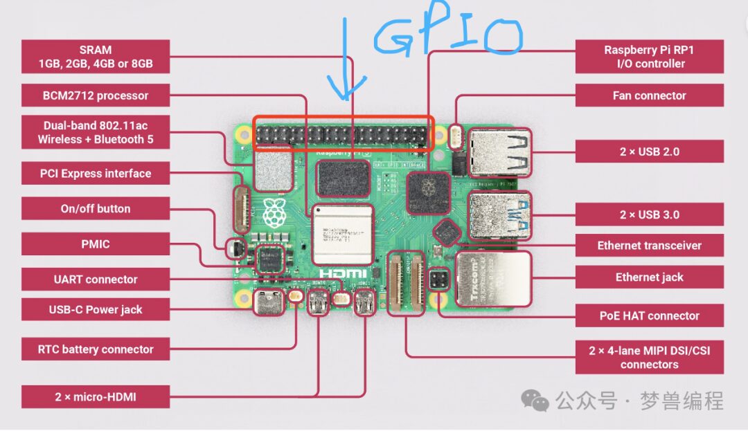
The GPIO pin interface is generally located at this position on the Raspberry Pi:
Practical Strategy: Start from Basics
We need to prepare some materials.
The Raspberry Pi supports 5V voltage output, but some electrical components may not withstand this voltage, so we also need a relay.
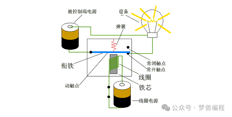
A relay is a key electrical component that allows a small current to control a larger current, commonly used to control devices like lights. Mastering the relay means mastering the control of the lights in this scenario.
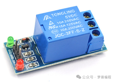
This time, we choose a “1-channel 5V relay”, where:
“1-channel” indicates it can control a single 220V line, meaning a single or a series of connected lights. “5V” refers to the relay’s operating voltage, which aligns perfectly with the Raspberry Pi’s 5V output, eliminating the need for an additional power source. Thus, the Raspberry Pi can directly provide the required voltage to activate the relay, allowing precise control of the device.
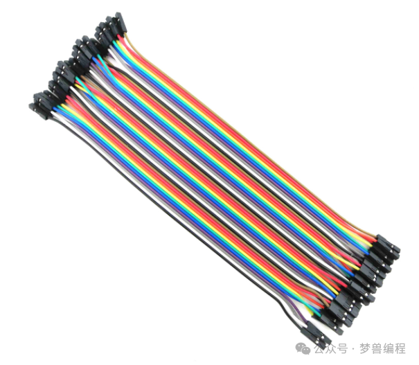
Dupont wires: a set of 40P costs a few dollars, and we only need three to connect the Raspberry Pi to the relay.
GPIO Pins Used in Raspberry Pi 5B
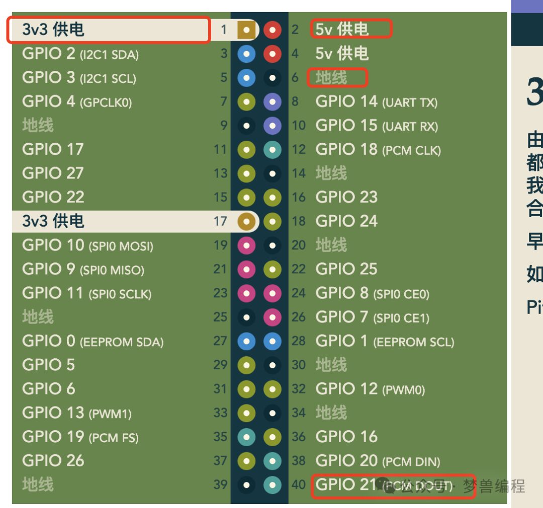
We will use the 5V power pin 2, ground pin 6, and GPIO pins 12 or 40.
The circuit connection diagram is as follows:
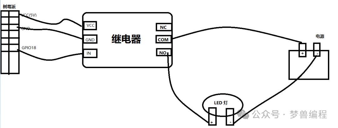
Note: GPIO18 corresponds to pin 12 in BCM encoding.
This wiring method is called the “Normally Open” wiring method, and there is another method called “Normally Closed”, which simply involves moving the “NO” live wire output to the “NC” position.
Writing the Program
Well, I am not yet very deep into Rust, so I will follow the popular Python example. Let’s run a simple application.
The Raspberry Pi system has a related IDE. The dependencies are already installed for us. Go to the menu -> Programming -> Thonny Python IDE and input the following code.
To accurately describe the relay’s workflow mentioned earlier, we can program according to the control logic discussed previously. Assuming the relay’s trigger coil is connected to GPIO 18 (BCM number), and that the relay has built-in status indicators—a red LED representing the relay’s power status and a green LED indicating whether the load circuit is on—we will write a Python script to simulate this process:
import RPi.GPIO as GPIO
import time

# BCM numbering method
GPIO.setmode(GPIO.BCM)
# Set GPIO pin 18 (which corresponds to pin 12 on Raspberry Pi) as output mode
GPIO.setup(18, GPIO.OUT)
# Turn on
GPIO.output(18, GPIO.HIGH)
time.sleep(5) # Turn off after 5 seconds
# Turn off
GPIO.output(18, GPIO.LOW)
# Finally, clean up GPIO pins
GPIO.cleanup()
This script follows the proposed control requirements, allowing the relay to respond to program instructions and achieve the desired functionality. When the program starts executing, a “pop” sound is heard as the red LED lights up, followed by the green LED indicating that the 220V light bulb has been activated. After 5 seconds, the same sound occurs as the green LED turns off and the 220V light bulb shuts down. Finally, GPIO.cleanup() ensures all GPIO pins return to a safe state for future use. Please ensure the circuit is correct before testing in a real environment to avoid damaging the equipment.
Note
Thank you for reading this far. If you found this article useful, please like and share. Perhaps others will find it useful too. 💖
Creating and maintaining this blog and related libraries involves a huge amount of work. Even though I love them, I still need your support. Or share the article. By sponsoring me, I can invest more time and effort into creating new content and developing new features. The best way to sponsor me is to check the ads on my WeChat public account.