
Click on the topElectrical Engineering Learning, follow and star it
A professional self-media in the field of electrical engineering, don’t miss it

Imagine a DC power supply with three pins on its output socket: positive, negative, and ground. Correspondingly, the load’s plug should also have three pins that match the power supply, so that energy can be supplied correctly.
Note that there are three essential conditions that must be met:
The first is that the shape, size, and pin diameter and length of the plug and socket must correspond to each other; otherwise, the connection cannot be completed. This stipulates the physical structure and pin definitions of the plug combination.
The second is that the output voltage of the power supply must meet the demand of the load side; otherwise, the electrical parameters cannot be satisfied. This determines the level specification of the plug combination.
The third is that the output impedance of the power supply must match the input impedance of the load; otherwise, power supply cannot be accomplished effectively. This determines the working nature of the power supply.
These three points are essentially the normative protocol of the power supply plug combination at the physical layer.
Now let’s look at communication interfaces. In the ISO/OSI model concerning computer information exchange, the physical layer is the lowest layer (Layer 1), which stipulates the mechanical appearance of the interface, pin definitions, interface levels, and byte formats.
The byte format refers to how many data bits are in a byte, how many start/stop bits there are, and how many parity bits there are. Generally, a byte has 8 data bits, 1 start bit (stop bit), and 1 parity bit. Note: start and stop bits can be combined.
Next, let’s look at the working mode of communication interfaces and networks.
When we make a phone call, we find that both parties can talk while also listening, which is called full duplex (two-way working mode); if one cannot listen while speaking, and cannot speak while listening, but both parties have the ability to speak and listen, which is the intercom style, this is called half duplex.
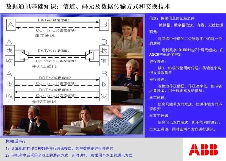
RS422 and RS232 interfaces are full duplex, while RS485 is a half duplex interface.
For half duplex interfaces, a communication initiator is evidently needed, so the RS485 interface and network must have a master station and several slave stations, and the number of slave stations is also specified. Generally, the number of slave stations is 32.
The relationship between the RS485 master and slave stations seems to be just a difference in communication working modes, but essentially, it is a reasonable distribution of control rights over the communication bus among the parties involved.
Now let’s look at bus connection issues.
Using the power supply as an example, we can draw a main line from the power supply, and then parallel several branches to supply several loads. As long as the power supply’s power requirements are met, this is evidently feasible.
If we use the same method to draw the RS485 communication line, is it feasible? The answer is no. We must first draw a line from the communication master to the first communication slave, then draw a second line from the first slave to the second slave, and so on until the last slave. At the end of the communication line, a terminal resistor must be added. If a disconnection occurs at any point on this communication line, the communication on subsequent links will also be interrupted. This wiring method is vividly referred to as the daisy chain connection method, while the power supply wiring method is called the star connection method.
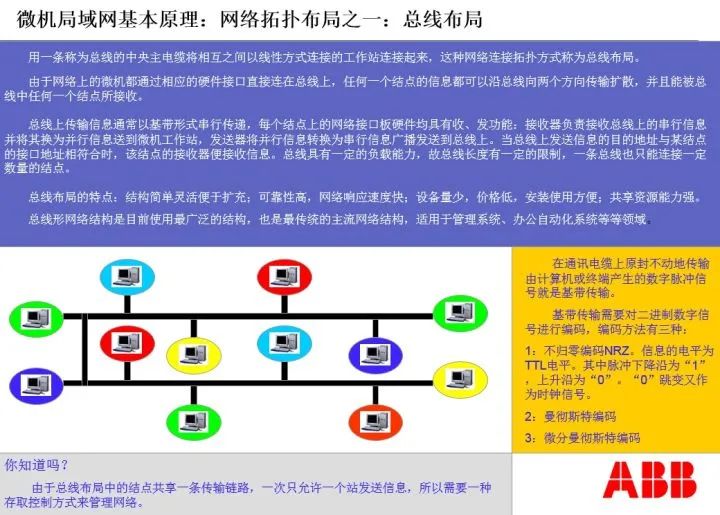
We find that from an electrical wiring perspective, the links are parallel. However, from a communication perspective, the links are daisy-chained, which is a sequential and orderly connection.
Now we can summarize:
The wiring method of the RS485 bus network must be a daisy chain connection, and it belongs to a half duplex communication method; RS232 is a point-to-point wiring method, belonging to full duplex communication. Whether it is the RS232 interface or the RS485 interface, they must comply with the communication protocols of the physical layer.
Next, let’s look at the MODBUS-RTU communication protocol:
Having a physical layer communication interface, does that mean communication can occur? The answer is no. The physical layer communication interface merely ensures that both parties have the conditions for communication. But if neither side can understand what the other is saying, or if their speaking styles and grammatical structures do not match, communication cannot occur.
In the OSI model, the data link layer is above the physical layer. The MODBUS-RTU protocol is a data link layer protocol; as long as both parties adopt the MODBUS-RTU protocol, it ensures that the communication language is in a format that both can understand.
Note the term “statement.” The physical layer defines bytes, which are equivalent to words in a language, while the data link layer organizes bytes into statements, i.e., frames.Frames define the grammatical structure of the statements used by both parties in communication.
MODBUS is also master-slave structured. Similar to the bus control at the physical layer, the master-slave relationship here regulates the control rights over the communication bus. The master sends a command first, occupying the bus; then it vacates the bus for the slave to write a response code; after the slave completes it, the bus is returned to the master.
Now, let’s take a look at the frame structure defined by ISO’s HDLC, which is the grammatical structure of communication statements, as follows:
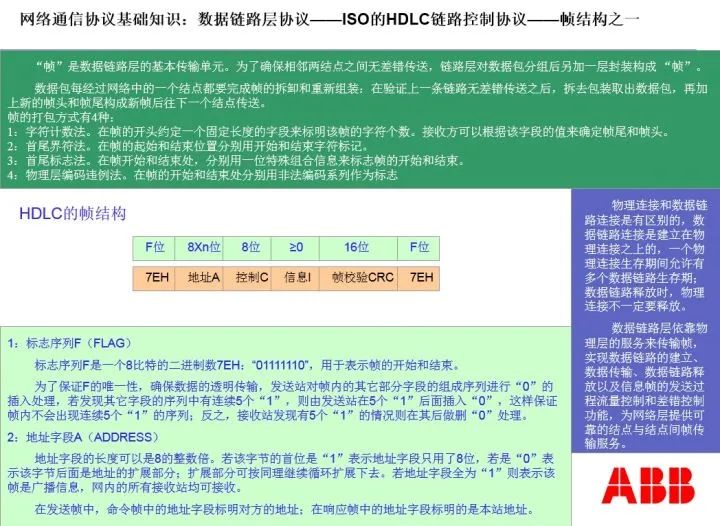
Under the MODBUS communication protocol, different command function codes have different frame structures. For the read register command, the frame structure of the MODBUS master is: 2 bytes of address code, 1 byte of function code, 2 bytes of data address code, and 2 bytes of CRC check code; the frame structure of the MODBUS slave response is: 2 bytes of function code, 1 byte of total bytes in the response area, N bytes of response data, and 2 bytes of CRC check code.
Although the physical layer protocol and data link layer protocol are different, the execution of the data link layer protocol must be based on the requirement that the physical layer connection between both parties has been met and that information exchange can occur without obstacles.
This rule must be completely and thoroughly executed in the seven-layer protocol of the ISO/OSI model. In the ISO/OSI model, the lower-level protocols of both parties must establish a transparent, fault-free connection and information exchange relationship for the upper-level protocols. In other words, the hierarchical relationship between levels must be absolute.
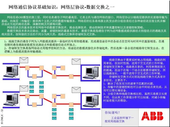
Above the data link layer is the network layer. Its task is to form the information exchange network of the field bus.
The functions of the network layer include: packaging communication frames into data packets and then sending data packets to the other party.
Since the network structures of both parties may differ, a bridge is needed to connect the same types of networks, while a gateway is needed to connect different types of networks.
There may be multiple channels between networks. When sending data packets, there are multiple paths to choose from. The component responsible for selecting the path is called a router. The router not only determines the actual data exchange network path but can also construct virtual network paths and determine the sending order of data packets. Therefore, the router is the most complex and critical equipment in the network layer.
In the OSI model, the physical layer + data link layer + network layer is collectively referred to as the field bus, and its communication interface is an 8-pin RJ45 crystal head. Clearly, RJ45 is completely different from RS232/RS485/RA422.
The data packets at the network layer are combinations of data frames. In simple terms, data packets are a short essay or a unit of data to be transmitted.
When sending data packets, the routing issues and receiving combination issues of the network layer are shown in the diagram below:
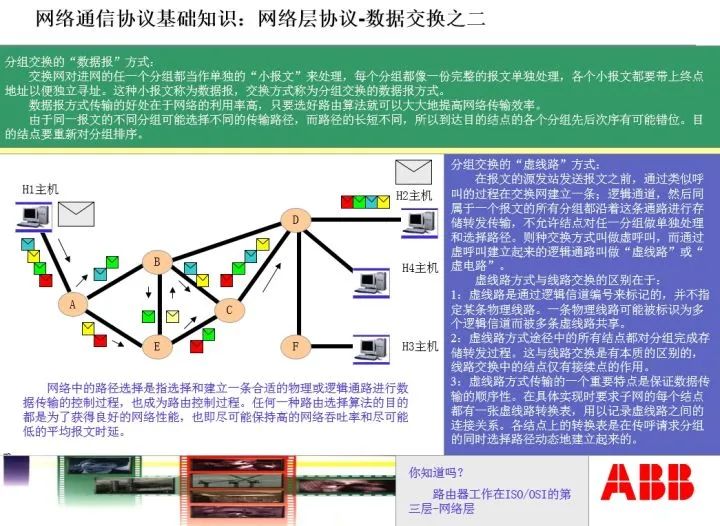
We see that in communication, the network layer first determines the routing path by the router, then sends the packets to the other party. After the other party receives the packets, it combines them in order and unpacks them into the actual document.
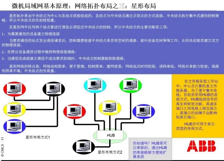
It is important to note: since the network layer has routers, the network layer supports star network structures.
Now let’s focus on the ISO/OSI seven-layer model, as follows:
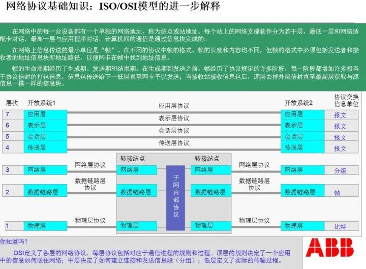
It should be clear that from the network layer upwards, the information units sent between layers are already complete messages. The OSI model also stipulates the grammatical structure of messages, which is omitted here for brevity.
It is worth noting that the communication interfaces of RS232/RS485/RS422 and their definitions are very clear. This includes the voltage levels of the pins, the functional definitions of the pins, and the data flow timing relationships during information transmission and reception, all of which must be accurate and strict, otherwise, information exchange cannot be executed.
When a PLC exchanges information with a certain power meter, and these power meters comply with the RS485/MODBUS-RTU communication specifications, what do we need to do?
The first step is to wire according to the daisy chain structure communication link requirements, connecting the PLC’s communication interface with N power meter interfaces. The last power meter’s end must be equipped with a 100-ohm terminal resistor.
The second step is to determine each of their addresses according to the principle of increasing addresses, such as 01H, 02H, 1FH, etc. Here, H indicates hexadecimal, and 1F represents 16 + 15 = 31.
The third step is to set the communication rate specified by the power meters in the PLC programming software.
The fourth step is to set the MODBUS communication codes according to the data area address codes of the power meters in the PLC programming software, as well as the cycling relationships of each slave station.
Note that the MODBUS communication codes here meet the IEC 61131-3 programming module requirements of the PLC. General PLC ladder diagrams do not have this function. Ladder diagrams meet the IEC 61131-1 requirements but do not meet the IEC 61131-3 requirements.
The fifth step is to allocate a dedicated data area in the PLC’s memory to store the information read from and processed from the power meters, so that a higher-level master station can read the information. This data area is called a data point table, sometimes abbreviated as communication protocol.
Finally, of course, it’s time for the power-on test. There are many details, which will not be introduced here due to space constraints.
Let’s look at an example of reading data using MODBUS-RTU on an RS485 network:
A certain power meter has an address of 01H. In the memory position 2000 of the power meter, there are six data points for three-phase current and three-phase voltage, each occupying two bytes, totaling 12 bytes.
The communication rate of this power meter is 9600 bps. What does this mean? Bps indicates bits, meaning that 9600 bits can be sent on this bus per second. We already know that a byte consists of 8 data bits, 1 start bit, and 1 parity bit, totaling 10 bits; thus, if the communication rate of the power meter is 9600 bps, then in one second, we can send: 9600/10 = 960 bytes.
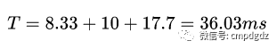
We also know that the frame structure for the master station to read data (downlink frame) includes 1 byte of address, 1 byte of function code, 2 bytes of memory address, 2 bytes of data quantity, and 2 bytes of CRC check code, totaling 8 bytes, so the time occupied by the master station sending the read data MODBUS communication frame is: 8X10/9600 = 8.33 milliseconds.
In this case, the MODBUS-RTU read data command is 0X03H, which means 03 command. Note the format here: 0X is the prefix, the middle 03 is the command, and the last H indicates hexadecimal.
The specific communication frame is: 01 03 07 D0 00 06 C5 45, where 0X01H is the address, 0X03H is the command, 0X07D0H is the memory address 2000, 0X0006H indicates reading six consecutive words, i.e., the current and voltage parameters in memory, and 0XC545H is the CRC check code for 01 03 07 D0 00 06.
So the response frame from the power meter (uplink frame) has the frame structure: 1 byte of address, 1 byte of function code, 1 byte of total bytes in the response area, 12 bytes of data, and 2 bytes of CRC check code, totaling 17 bytes, with a time occupied of: 17X10/9600 = 17.7 milliseconds.
The specific response communication frame from the meter is: 01 03 0C 00 64 0064 0064 00 DC 00 DC 00 DC D6 F5, where 0X01H and 0X03H have the same meanings as above, 0X0CH indicates that there are 12 bytes in the uploaded data area, 0X0064H indicates that phase A current is 100A, the following two groups are phase B and C currents, both are 100A, 0X00DCH indicates that phase A voltage is 220V, and the following two groups are phase B and C voltages, both are 220V, and finally, 0XD6F5H is the CRC check code.
From the master station initiating the downlink communication frame, waiting for 10 milliseconds for the slave to respond, to receiving the uplink communication frame from the slave, the total duration is:
If there are 31 identical meters waiting for the master station to access one by one, the total duration from the master station starting to access the first meter to the last response is:
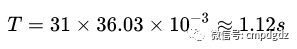
The 1.12 seconds here is the reading data cycle for these 31 meters at a communication rate of 9600 bps, and it ignores the waiting time for the master station to send the downlink communication frame again, so the actual time will be slightly longer.
We believe that by now, everyone should have a deeper understanding of the communication frames under MODBUS-RTU.
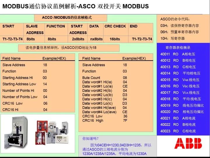
Let me remind you: a word consists of two bytes. Generally, a byte can only express 8 switching quantities. However, for analog quantities, a word must be used to express them. For example, 1250A current in hexadecimal is 04E2H, which requires 2 bytes to express completely. Thus, in various power meters, analog quantities are expressed using words.
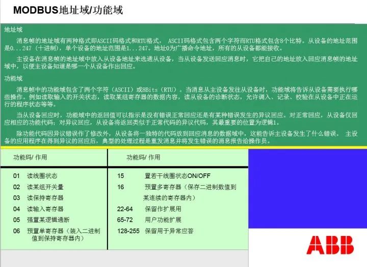
Below are some commonly used function codes of MODBUS, i.e., command codes:
Below are examples of the downlink and uplink communication frames of the PLC reading data from the dual throw switch ASCO controller:
Let’s clarify a few related issues:
1) Some field buses use tokens to solve the control rights issue of the bus.
It’s easy to think that if a slave has an urgent matter that requires the master’s service, but MODBUS stipulates polling rules, waiting for its turn may be too late. Therefore, many field buses have invented a special thing called a token. The token is short, only one byte, and can be quickly transmitted on the bus. Tokens are passed among stations; whoever gets the token becomes the master and can publish information. If the station has nothing to publish, it passes the token to the next station, thereby solving the bus occupancy issue.
2) When a link is disconnected, to avoid communication interruption, dual master measures can be adopted. Two master stations (PLC’s two master RS485 interfaces) are connected with a handshake line; usually, the primary RS485 is activated while the auxiliary RS485 is floating. The floating RS485, although connected to the bus, is in a high-impedance state equivalent to complete disconnection. When a disconnection occurs, the slave confirms and immediately activates communication, connecting from both ends of the link.
Sometimes, ring communication measures are also adopted. Due to space limitations, I will not introduce them here.
3) MODBUS can work at the network layer, at which point the protocol changes to MODBUS-TCP, but it still complies with the master-slave structure.
4) The MODBUS protocol was invented by the American Modicon company, whose purpose is: the MODBUS protocol is a free and open protocol. Later, Modicon was acquired by Schneider Electric, which inherited Modicon’s practice, and MODBUS remains a free and open protocol. Since MODBUS has become Schneider’s protocol, Schneider extended it to the network layer, constructing the MODBUS-TCP protocol at the network layer, as well as the proprietary MODBUS-PLUS protocol. Due to space constraints, descriptions of these two protocols are omitted here.
5) About the differences between RS232 and RS485
Those who have studied analog and digital electronics know about differential circuits. Differential circuits have common mode rejection ratios that can eliminate common mode errors. The RS485 interface has this characteristic. Therefore, the transmission distance of the RS232 interface is only a few meters, while the transmission distance of RS485/RS422 interfaces is 1200 meters.
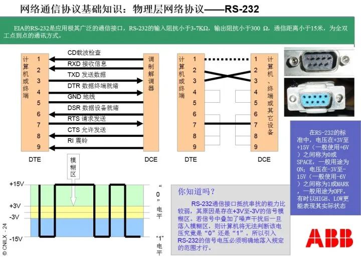
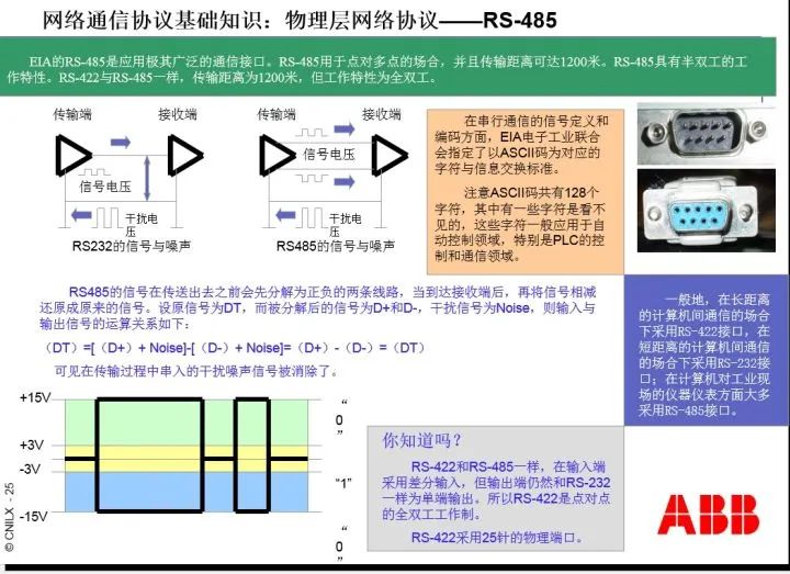
We see from the diagram that although the shapes of RS232 and RS485 interfaces are identical, their performance and information exchange modes are different, thus their anti-interference capabilities are also different.
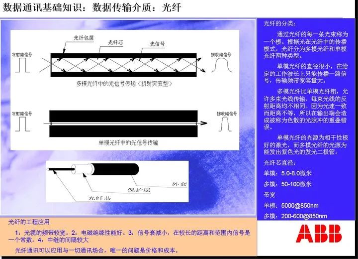
6) When the distance is long, the RS485 interface can also connect to fiber optics, but it requires a pair of fiber optic converters. The reason for a pair is that one is used for electrical-to-optical conversion, while the other is for optical-to-electrical conversion. The communication medium between the fiber optic transceivers is fiber optic or optical cable. (Note that fiber optics are the core of optical cables, do not confuse them as two different things.)
Fiber optics are divided into single-mode and multi-mode. Single-mode fibers are thinner and have less reflection during transmission, resulting in less distortion, and their transmission distance can exceed 15 km; multi-mode fibers are thicker, have more reflection during transmission, resulting in greater distortion, and their transmission distance is 1.5 km.
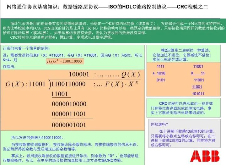
7) The CRC check code is a binary division without borrowing, used to check whether the received information has errors.
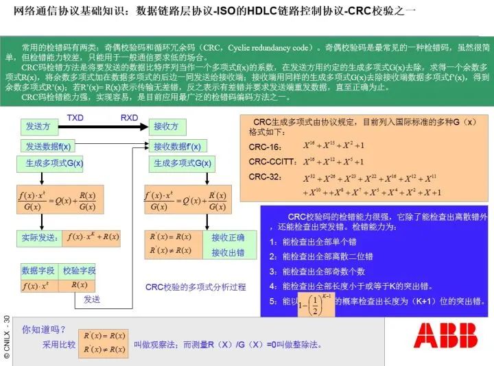
Note that here f(x) refers to the MODBUS communication frame without the CRC check code, with the divisor being CRC16. The CRC in the frame is the remainder after the calculation.
Before sending the frame, the master station calculates the CRC for the frame and attaches the remainder of the CRC calculation to the end of the frame before sending it to the slave. After the slave receives the frame, it first performs a CRC calculation on the frame, excluding the CRC part, to check whether it is correct; if not, the slave requests the master to resend.
Similarly, when the slave sends information to the master, the master also checks the correctness of the data based on the CRC. If an error is found, it requests the slave to resend.
8) About MODBUS-RTU, MODBUS-ASC, and MODBUS-TCP
If the way of expressing data in MODBUS uses BCD code, it is called MODBUS-RTU; if it uses ASCII code, it is called MODBUS-ASC; if MODBUS operates at the network layer, it is called MODBUS-TCP.
The content of ASCII code is as follows:
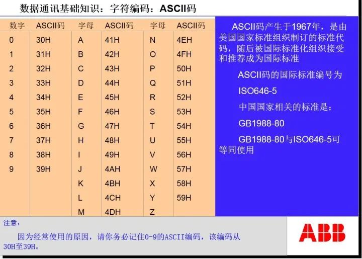
In practical use, most MODBUS applications utilize BCD code, hence MODBUS-RTU is widely used.
Below is the BCD code:
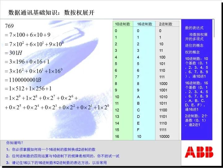
It is important to note that in protocol usage, the values in the data frames are expressed in hexadecimal. For example, a 100A current is written as 0X64H, while a 380V voltage is written as 0X17CH.
9) About the twisted communication lines and grounding used in RS485 networks
We know that there will be distributed capacitance between two parallel cables, and distributed capacitance will weaken the signal strength. To eliminate distributed capacitance, the two parallel wires of the communication line need to be twisted together at a specific length, which is called twisted pair cable. The twisting length of twisted pair cable is standardized and closely related to the communication rate. In practical use, the appropriate twisted pair cable should be selected according to the communication rate.
The outer layer of twisted pair cable has a shielding layer. The shielding layer must be grounded at a single point and must not be grounded at both ends at the same time to prevent ground currents from causing interference. In actual wiring, independent grounding for each wire segment should be adopted, and it is important to avoid the practice of connecting the shielding layers of all wire segments to a common ground.
10) About the daisy chain communication link connection method
There is no absolutely daisy-chained network. In fact, in the communication network constructed using the daisy chain wiring method, each node is a terminal, connected to each slave station through twisted pair cables, and these twisted pairs form a similar star structure. We might as well refer to this wiring method as quasi-star wiring in the daisy chain network.
Engineering practice has shown that the length of quasi-star wiring should not exceed 70 cm. If it exceeds, communication instability may occur.
In fact, 70 cm has also become an unwritten quality inspection standard in the industry.
A 100-ohm terminal resistor can be added or not when the communication rate is low, but when the communication rate is high (above 19.2 kbps), it is recommended to add it. For example, in the RS485 network under PROFIBUS, the terminal resistor has been built into the terminal device, and it can be added or removed simply by toggling a switch.
The purpose of the terminal resistor is to absorb reflected waves.
When we tightly tie a rope between two trees and then hit one side of the rope, we will see a propagating wave going to the other end and also see a reflected wave. If the hitting frequency is appropriate, a standing wave will appear in the middle of the rope.
For communication, whether reflected waves or standing waves will severely affect communication quality. Terminal resistors are used to absorb reflected waves and can elevate the final slave station’s signal level.
Both RS485 and MODBUS concepts need to be mastered through practice; it is difficult to understand and grasp them solely by reading text. If this article can benefit your practical activities, I would be very pleased.
Source: Zhihu Q&A, Teacher Zhang Baifan