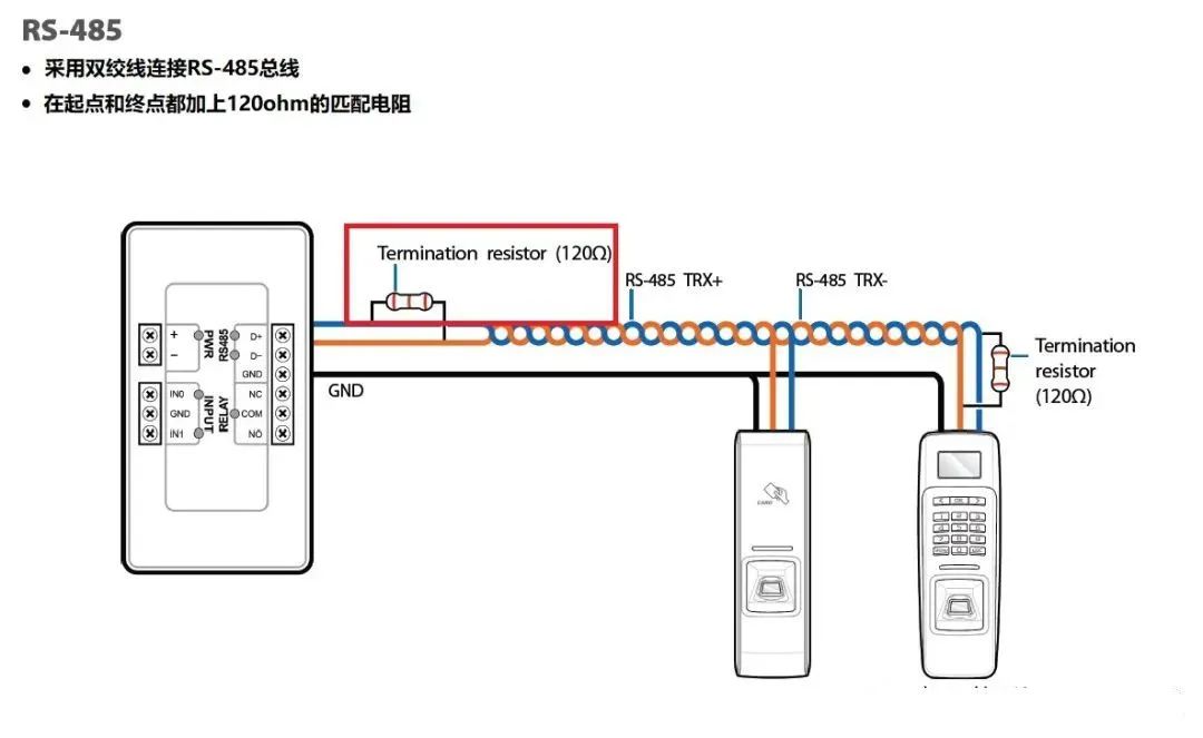
The RS485 bus has advantages such as simple structure, long communication distance, fast communication speed, and low cost. It is widely used in industrial communication, power monitoring, instrumentation, and other industries.
Due to the harsh industrial control environment, there is more interference coupling in the communication lines, which affects the reliability of the RS485 bus and may even damage the RS485 transceiver chip.
Impulse group interference is a common type of interference. Electrical fast transient (EFT) immunity testing is often used to simulate interference and verify system reliability.

1. Sources of Impulse Group Interference
In industrial control environments, instantaneous interference often occurs due to lightning, short circuits, and switching actions with inductive loads. These interferences are short bursts of high-energy pulse disturbances characterized by clusters of pulses, short rise times, and high repetition frequencies.
These disturbances couple onto the RS485 bus, and since these pulses are not single pulses but a series of pulses, they accumulate on the RS485 bus, causing the voltage amplitude of the disturbance to exceed the noise tolerance of the RS485 transceiver, leading to communication errors.
Furthermore, since the cycle of these pulse disturbances is relatively short, with brief intervals between each pulse, when the first pulse disturbance has not yet dissipated, the second pulse follows closely behind. For the parasitic capacitance on the RS485 bus and the junction capacitance of the RS485 transceiver, this leads to recharging before complete discharging, and because parasitic capacitance is usually small, even a small amount of energy can reach a high voltage, easily damaging the RS485 transceiver and affecting the reliability of RS485 bus communication.

2. Principles of Impulse Group Interference Generation
The voltage magnitude of the impulse group interference source depends on factors such as the inductance of the load circuit and the speed at which the load is disconnected.
For example, in the case of a switch operation, when the switch is opened, the distance between the static and dynamic contacts is relatively close, and the back electromotive force induced by the inductance in the circuit is sufficient to break down the air gap between the contacts, causing the circuit to conduct. However, this discharge process is very brief, during which a leading pulse of nanoseconds is generated, with a width reaching several tens of nanoseconds and an amplitude exceeding several kilovolts. After this pulse ends, the circuit begins to repeat the process of generating back electromotive force due to the inductive load and discharging through the air gap between the static and dynamic contacts of the switch.
This process continues until the energy stored in the inductive load is sufficiently low that it can no longer produce the aforementioned discharge process.
These disturbances couple onto the RS485 bus, creating significant interference that affects communication reliability.

3. Measures to Improve Immunity to Electrical Fast Transient Group Interference
The immunity to electrical fast transient group interference is a common mode interference, which can be suppressed through filtering, absorption, or isolation methods.
Isolation of the RS485 Bus
The main functions of bus isolation are as follows:
(1) Ensuring the safety of equipment and personnel—impact of high voltage
RS485 is used for communication between devices, and often, developers do not know what type of device their customers are connecting their equipment to. If the other party uses a simple resistor-capacitor voltage divider to reduce 220V to 12V with no isolation from the power grid, testing, debugging, and usage can be very dangerous. If the insulation of high-voltage equipment is damaged, high voltage on the RS485 line can threaten both equipment and personal safety.
(2) Preventing abnormal reception at remote ends—impact of potential difference
In many practical applications, communication distances can reach several kilometers, and the distance between nodes is quite far.
Designers often connect the reference ground of each node directly to the local ground as the return ground for signals, which seems like a normal and reliable practice. However, the ground is not an ideal “0” potential; it is also a conductor and has impedance.
When large currents flow through the ground, there will also be a potential difference across the ground at the ends where the current flows.
For example, in the diagram below, due to the distance between A and B, the reference grounds are not at 0 potential, and the impedance of the ground is not 0. Due to the current loop effect, the voltage at point A is Vs, while at point B it becomes Vc + Vs.
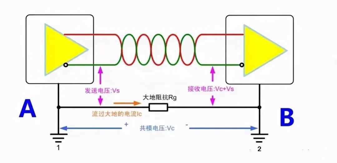
▲ Figure 1. Impact of Potential Difference
(3) Avoiding data anomalies and device damage—impact of ground loops
Since there is a potential difference in the ground between nodes, wouldn’t it be enough to connect the ground of the two nodes with a single wire?
This is a big mistake! Doing so would only worsen the situation; this long wire would form a massive ground loop with the ground! As you may have learned in school, a closed loop in a changing magnetic field will generate current.
50Hz AC power lines and large motors are sources of AC magnetic fields. If the bus is close to or passes through these areas, the ground loop can generate currents of several amperes or even hundreds of amperes.
The common-mode voltage generated by the current flowing through the ground loop will affect normal communication on the bus. In addition to stable magnetic field sources, transient interferences like surges from power lines, lightning strikes, and high-frequency noise can also be picked up by this giant “loop antenna,” causing communication anomalies.
Adding Ferrite Beads to Absorb Interference
Adding ferrite beads at the device entrance can effectively absorb interference, and increasing the number of turns of the communication line through the ferrite bead can enhance the absorption effect,
as shown in Figure 2, adding ferrite beads near the RS-485 interface of the device under test.
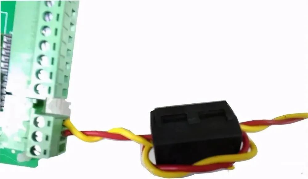
▲ Figure 2. Adding Ferrite Beads to the Communication Line
Using Shielded Twisted Pair Cable
As shown in the figure, in practical applications, RS485 communication lines can use shielded twisted pair cables, with the shield connected to ground at one point, effectively suppressing the coupling of electrical fast transient group interference onto the communication line.
▲ Figure 3. Using Shielded Twisted Pair Cable
Adding TVS to the RS-485 Bus for Ground Protection
When adding a TVS diode between A and ground, and B and ground, if the electrical fast transient group interference voltage coupled onto the RS485 bus is relatively high, the interference voltage will be clamped by the TVS, protecting the RS485 transceiver.
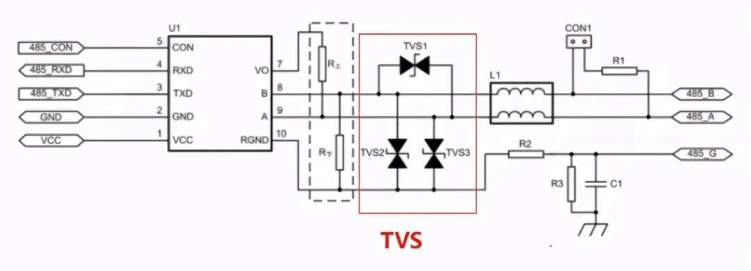
▲ Adding TVS for Overvoltage Protection
RS-485 Bus with Series Ferrite Beads
Since ferrite beads act as resistors at high frequencies, they will convert high-frequency energy into heat and dissipate it.
Therefore, connecting ferrite beads in series on the RS485 bus will consume the energy of the electrical fast transient group signal coupled onto the RS485 bus, enhancing the anti-interference capability of the RS485 bus.
Complete question bank for the 2021 electrician junior exam (includes answers)
Is troubleshooting frequency converter faults difficult? Just one click!
Can you brush through all electrical exam questions with one click? Don’t you have this amazing tool yet?
Which of the five major electrical drawing software (CAD, Eplan, CADe_simu…) do you pick?
Latest electrical version of CAD drawing software, with a super detailed installation tutorial!
Latest electrical drawing software EPLAN, with a super detailed installation tutorial!
Common issues for beginners using S7-200 SMART programming software (with download link)
Comprehensive electrical calculation EXCEL spreadsheet, automatically generated! No need to ask for electrical calculations!
Bluetooth headphones and introductory books on electrical engineering/PLC are available? Come and claim your electrical gift!
Basic skills in PLC programming: ladder diagrams and control circuits (with 1164 practical cases for Mitsubishi PLC)
Still can’t read electrical diagrams? Take the basics of electrical diagram recognition and simulation software, and get hands-on quickly!
12 free electrician video courses, 10GB of software/e-book materials, and 30 days of free electrician live classes are being given away!