MODBUS
Modbus is a serial communication protocol created in the late 1970s by Modicon (now Schneider Electric) for use with its programmable logic controllers (PLCs). Modbus is the most common industrial control protocol, primarily because it is an open, simple, and powerful protocol that can be used freely without any royalties. Since the introduction of Modbus, the protocol has been ported to work over Ethernet. To achieve this, the serial-based protocol is encapsulated (essentially “wrapped”) in the header of TCP data and transmitted over Ethernet networks via the default TCP port 502. Due to its ease of use, Modbus can be found in various factories and even in substations.
Modbus
Frame packets can be divided into two parts: Application Data Unit (ADU) and Protocol Data Unit (PDU). The ADU consists of an address, PDU, and error-checking method. The PDU consists of a function code and the data segment of the Modbus frame. Figure 5-1 is an example of the Modbus serial protocol, also known as Modbus RTU. (Translator’s note: The ADU contains the PDU, and they have an inclusion relationship.)
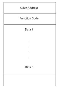
Figure 5-1 Modbus RTU
The Modbus RTU protocol differs from all other implementations of Modbus, including Modbus+, Modbus ASCII, Modbus TCP/IP, Modbus over TCP/IP, and other less common implementations of Modbus. Our focus will be on Modbus TCP/IP. One major difference between Modbus TCP/IP and Modbus over TCP/IP is that Modbus TCP/IP does not include a checksum in the payload of the packet, as is the case in Modbus RTU.
Modbus TCP/IP consists of ADU and PDU, very similar to Modbus RTU. However, in Modbus TCP/IP,
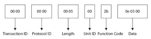
Figure 5-2 MBAP and PDU
The ADU consists of the Modbus Application Header (MBAP) and PDU. The MBAP header consists of Transaction ID, Protocol ID, Length, and Unit ID. The PDU has the same structure as the PDU in Modbus RTU, with function code and data payload. The function code (FC) in the packet helps determine the nature of the packet. For example, the function code shown here is 0x2b (43), which is for reading device identification FC. This FC requests specific information from the device, such as the manufacturer and model of the PLC.
For different FCs, the data portion of the packet represents different information. For the read device identification FC, the data tells the device which part of the identification is being requested. Using Nmap, you can use the modbus-discover Nmap script (https://nmap.org/nsedoc/scripts/modbus-discover.html) for brute-force collection. The modbus-discover Nmap script also attempts to collect Slave ID information. Slave ID information is read via FC 17 (0x11). The Modbus standard includes function codes that most devices will support. These function codes are defined in the Modbus standard, as shown in Figure 5-3.
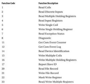
Figure 5-3 Modbus Function Codes
As an older protocol, Modbus lacks most modern security features and is even vulnerable to trivial attacks such as unauthenticated command sending and packet replay attacks. With each function code, the data portion of the packet changes, so it contains the appropriate information being requested. As an example, in the read request for Modbus coils with function code 1, the data portion of the packet contains the reference number, which is the starting point for reading and the number of coils to read. Figure 5-4 is an example of a packet in Wireshark:
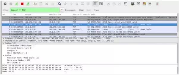
Figure 5-4 Modbus Request Response Example
There are various techniques to read and write Modbus coils and registers. You can use programming languages like Python to manually handle packets, as the packets are very simple, and libraries such as pymodbus can assist you in constructing, receiving, and parsing packets. Another tool that simplifies packet operations is scapy (http://www.secdev.org/projects/scapy/). Of course, in most cases, the simplest and quickest method is to use client tools that have already implemented the Modbus protocol. Here, we recommend a tool suitable for penetration testers, modbus-cli (https://github.com/tallakt/modbus-cli). It allows you to read and write coils and registers using simple commands, as shown in Figure 5-5:
One of the challenges of penetration testing Modbus devices is identifying the functionality of each coil and register. Unlike many protocols, the Modbus protocol does not record the significance of the values read and written. Depending on your target, you can perform more tests to gather more information about the logic executed by the devices. By using simulator systems like CybatiWorks (https://cybati.org/cybatiworks), you can attempt to perform tests and gather information on non-production systems. Using a Human-Machine Interface (HMI), the effects of changing coils and registers become more apparent. Below, we use CybatiWorks to simulate a traffic light control panel example, which has a very simple HMI, allowing you to see that the system is in automatic mode.
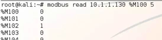
Figure 5-5 View Registers
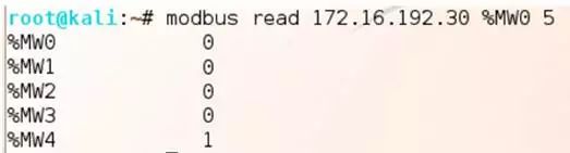
Figure 5-6 Registers Storing Mode Information

Figure 5-7 Cybatiworks Simulator
By modifying settings and traversing the values of the queried registers, you can identify which register is associated with the system’s mode settings (this process is somewhat similar to the behavior of doing game hacking with CE). This process can take some time, and it may also lead to errors when you query invalid addresses in the system. As shown in Figure 5-7, through the above steps, we found that setting the register %MW4 to a value of 1 puts the system in automatic mode, causing the indicator lights to change at a given frequency.
You may want to change the mode of the system so that the device does not change the traffic lights on a timer. To achieve this effect, you might want to modify the value of register %MW4 to zero. However, in this case, the device cannot disable automatic mode with a single data write. Through testing, we believe this phenomenon may be caused by the device’s internal logic. To disable automatic mode, a specific indicator light needs to be turned on first. We used a write command to invert the values of all registers except for %MW3. The reason for keeping %MW3 is that it maps to the flashing button on the HMI; regardless of the state of the other registers, as long as %MW3 is set, all indicator lights will flash. After completing the above steps, setting %MW4 to zero will disable the setting in the HMI. Figure 5-8 shows the status of values after the write command is issued.
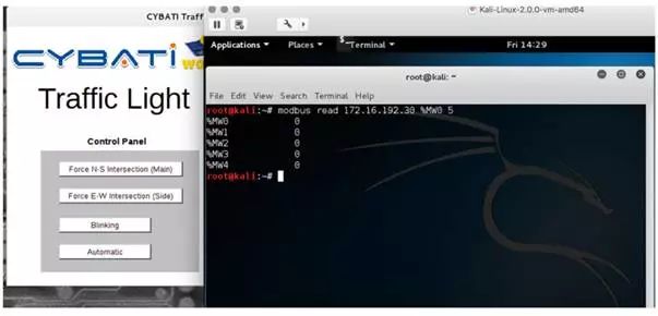
Figure 5-8 Register Values After Write Command
Man-in-the-Middle Attack on Modbus Protocol
-
Popularity: 10
-
Difficulty: 8
-
Impact Surface: 8
-
Threat Score: 9
Due to the lack of security in its design, the Modbus protocol is vulnerable to Man-in-the-Middle (MiTM) attacks, including packet replay attacks. The attack method against the Cybati traffic light system mentioned earlier can also be used for man-in-the-middle attacks. In the attack, the attacker can also deceive the HMI to make the traffic light system appear normal, delaying the vendor’s discovery of the issue. Various open-source or commercial tools can be used to execute man-in-the-middle attacks on Modbus networks. Modbus VCR (https://github.com/reidmefirst/modbus-vcr/) is an open-source free tool that uses Ettercap to record Modbus traffic and then replays that traffic, making the system appear to be processing normal traffic.
High-risk Command Words for Schneider PLC
-
Popularity: 10
-
Difficulty: 8
-
Impact Surface: 8
-
Threat Score: 9
Implementations of the Modbus protocol often include some non-standard function codes implemented by vendors. A typical example is the function code 0x5a (90) in Schneider PLCs. Like most proprietary protocols, you must use engineering software to analyze how the protocol works. The industrial control security research and consulting company Digital Bond first pointed out the issue with function code 0x5a in a Metasploit module (https://www.rapid7.com/db/modules/auxiliary/admin/scada/modicon_command) in the well-known Project Basecamp. This high-risk function code implements functions not allowed by the Modbus standard, such as terminating the CPU’s operation. This high-risk function code was discovered by recording the communication traffic between engineering software (Unity Pro) and the Modicon PLC.
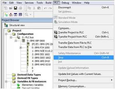
Figure 5-9 Unity Pro Menu Item
Through packet replay, it can be seen that this command word terminated all operating logic of the Modicon PLC. For systems requiring real-time control, such attacks can have disastrous consequences.
Recording the communication between engineering software and the PLC can provide useful information from the protocol. In the case of executing function code 90, the PLC leaked surprising information, as shown in Figure 5-10, including the machine hostname of the last program loaded onto the device. When examining the traffic captured from the PLC and engineering software, Modbus often contains unencoded strings, making it easy to parse from the device’s response.
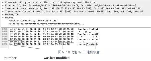
In this example, the project name is “Project”, and the hexadecimal value is “\x50\x72\x6f\x6a\x65\x63\x74”. Further inspection of the packet reveals that the hexadecimal “\x08\x00\x00” is little-endian and seems to be the project revision number, which when interpreted by the program, displays as 0.0.8. “\x0c\x3b\x0c\x0e\x01\xde\x07” is the date of the last modification of the project file. The timestamp shown below is in little-endian format, measured in hours, minutes, seconds, days, months, and years.
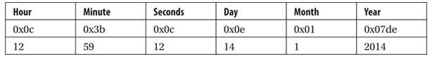
Figure 5-11 Timestamp
Identification of Schneider PLC
-
Popularity: 10
-
Difficulty: 8
-
Impact Surface: 3
-
Threat Score: 7
Using the same technique, Digital Bond’s Project Redpoint (https://github.com/digitalbond/Redpoint/blob/master/modicon-info.nse) can collect more information from the PLC, including the location of the PLC deployed within the industrial facility. Utilizing Modbus Nmap scripts to gather information helps build device profiles, which communicate with Modbus using function codes 43 and 90. We can safely retrieve information from the device using the built-in commands (function codes 43 and 90).
This article was translated by Kanxue Forum ljcnaix .
For reprint, please indicate the source as Kanxue Forum.
If you liked it, don’t forget to give it a thumbs up!
Popular Reading Articles:
-
5 Reasons to Choose Kanxue Enterprise SRC
-
Beginner’s Guide to Windows Kernel Exploitation (Part 2): Familiarizing with HEVD
-
Beginner’s Guide to Windows Kernel Exploitation (Part 1): Setting Up the Experimental Environment
-
Analyzing the Dirty Cow Principle from the Kernel Perspective
-
[Resources] Online Practice Platform for Web Security
-
……
For more excellent articles, long press the QR code below, “Follow Kanxue Academy WeChat Account” to view!

Kanxue Forum: http://bbs.pediy.com/
WeChat ID: ikanxue
Weibo: Kanxue Security
Business Cooperation: [email protected]