Overview of RS232
The RS-232 interface complies with the serial data communication interface standard established by the Electronic Industries Alliance (EIA). The original designation is EIA-RS-232 (abbreviated as 232, RS232). It is widely used for external connections of computer serial interfaces, including connection cables, as well as mechanical, electrical, signal, and transmission processes.
The RS-232-C standard specifies data transmission rates of 50, 75, 100, 150, 300, 600, 1200, 2400, 4800, 9600, and 19200 baud per second.
Characteristics of RS232
RS-232 is one of the mainstream serial communication interfaces. Due to the early emergence of the RS232 interface standard, it inevitably has some shortcomings, mainly including the following four points:
- The voltage on any signal line of the RS232 interface is in a negative logic relationship. That is: logic “1” is -3 ~ -15V; logic “0” is +3 ~ +15V, with a noise margin of 2V. Therefore, the receiver needs to recognize a +3V signal as logic “0”, a signal below -3V as logic “1”, and a 5V TTL level as logic “1”, while recognizing 0 as logic level. It is incompatible with TTL levels and requires a level conversion circuit to connect to TTL circuits.
- Low transmission rate. In asynchronous transmission, the bit rate is 20Kbps; therefore, in the 51CPLD development board, the integrated program baud rate can only be 19200, which is also the reason.
- The interface uses signal lines and signal return paths, forming a common ground transmission form. This standard ground transmission is susceptible to common-mode interference, resulting in weak noise resistance.
- Limited transmission distance. The maximum transmission distance is 50 feet, which is about 15 meters.
Overview of RS485
The RS-485 serial bus is used for communication distances that must range from several meters to several kilometers. RS-485 uses balanced transmission and intermittent reception, which can suppress common-mode interference. In addition to the high transceiver, it can also detect voltages as low as 200mV, thus restoring transmitted signals over kilometers. RS-485 uses a half-duplex mode, meaning only one point transmits at a time. Therefore, any transmitting circuit must be controlled by an enable signal.
Characteristics of RS485
RS-485 is very convenient for multipoint interconnection, saving many signal lines. RS-485 applications can form a diversified system through Ethernet, allowing up to 32 drivers and 32 receivers to be connected in parallel. In response to the shortcomings of RS-232, the new standard RS-485 has the following characteristics:
- The electrical characteristics of RS-485: logic “1” is represented by a voltage difference of +2V to +6V between the spare lines, while logic “0” is represented by a voltage difference of -6V to -2V between the spare lines. The interface signal levels are lower than those of RS-232, making it less likely to damage the interface circuit chips. This level is compatible with TTL levels; otherwise, it connects with TTL circuits.
- The maximum data transmission rate is: 10Mbps
- The RS-485 interface uses a combination of balanced drivers and differential receivers, providing good resistance to common-mode interference, i.e., good noise performance.
- The maximum transmission distance of the RS-485 interface is 4000 feet, practically reaching 3000 meters.
- RS-232 interfaces only allow one transceiver user to connect to the access point, i.e., single-station functionality. In contrast, RS-485 interfaces allow up to 128 transceivers to connect at the access point, i.e., multi-station capability. A single RS-485 interface can quickly establish a device network.
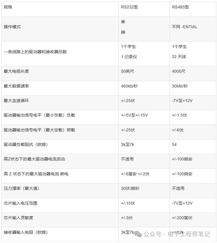
Differences Between RS232 and RS485
- Working mode: RS232 is full-duplex, while RS485 is half-duplex.
- Transmission method: RS485 and RS232 are merely physical protocol communications (i.e., interface standards); RS485 is a differential transmission method, while RS232 is a single-ended transmission method, but there is no strict distinction in communication protocols.
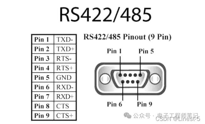
- Signal lines: The half-duplex network formed by the RS485 interface generally requires only two signal lines. The RS-232 interface typically uses three lines: RXD, TXD, and GND.
- Interference resistance: The RS485 interface uses a combination of balanced drivers and differential receivers, providing good interference resistance. The RS232 interface uses braided signal lines and braided signal lines to form a common ground transmission form, which is easily susceptible to common-mode interference.
- Transmission distance: The maximum standard transmission distance for RS485 is 1200 meters (at 9600bps), practically reaching 3000 meters. RS232 has a limited transmission distance, with a maximum standard distance of 50 meters, practically only usable up to about 15 meters.
- Communication capability: The RS485 interface allows up to 128 transceivers to connect at the interface, enabling users to easily establish a device network using a single RS485 interface. RS232 only allows one-to-one communication.
- Transmission rate: RS232 has a lower transmission rate, with a baud rate of 20Kbps in asynchronous transmission. The maximum data transmission rate for RS485 is 10Mbps.
- Electrical level values: The logic “1” of RS485 is represented by the voltage difference of +(2-6)V between the two lines; logic “0” is represented by the voltage difference of -(2-6)V between the two lines. In RS-232, the voltage of any signal line is primarily negative logic. That is: logic “1” is -(5-15)V; logic “0” is +(5-15)V.
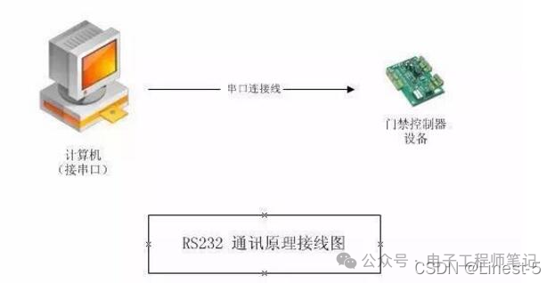
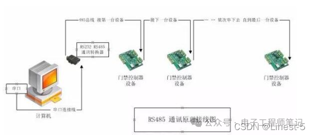
PCs are already equipped with RS232 and can be used directly. If using RS485 communication, simply connect an RS232 to RS485 converter to the RS232 port, eliminating the need for programming.
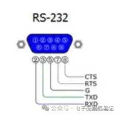
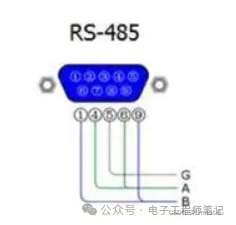
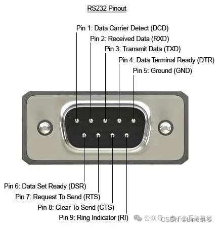
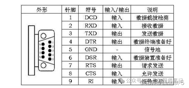
RS232 is a standard interface with a D-shaped 9-pin configuration. The signal definitions of the connected device interfaces are the same. The signal definitions are as follows:
RS232 only allows single communication (single-station functionality).
The RS485 interface allows up to 128 transceivers on the link (multi-station functionality).
Communication distance: The theoretical distance between the farthest device (controller) and the computer is 1200 meters. It is recommended to keep it within 800 meters, with the best control within 300 meters. If the distance is too long, a 485 repeater (extension) can be used, with the repeater placed at the link or intermediate starting point. Theoretically, the repeater can reach 3000 meters.
Load number: The number of devices (controllers) that can be connected to 485 depends on the communication chip of the controller and the communication chip of the 485 converter. Typically, there are options for 32, 64, 128, and 256. These options are theoretical numbers. In practical applications, the load number may not reach the specified number due to environmental factors, communication distance, etc.
485 communication wiring (must be twisted pair or one of the network cables); if ordinary wires (non-twisted) are used, interference will be significant, making communication impossible.
Each controller device must participate and cannot have star connections or branches. If there are star connections or branches, the effect will be significant, communication will be poor, and even transmission may be impossible.
Summary of Differences