M-Bus Multi-Master to Modbus RS232 (RS485) – ADFWEB Converter – Guangzhou Xinyu IoT
Author: Zou Wuyi Mobile 185-020-77899Email: [email protected]
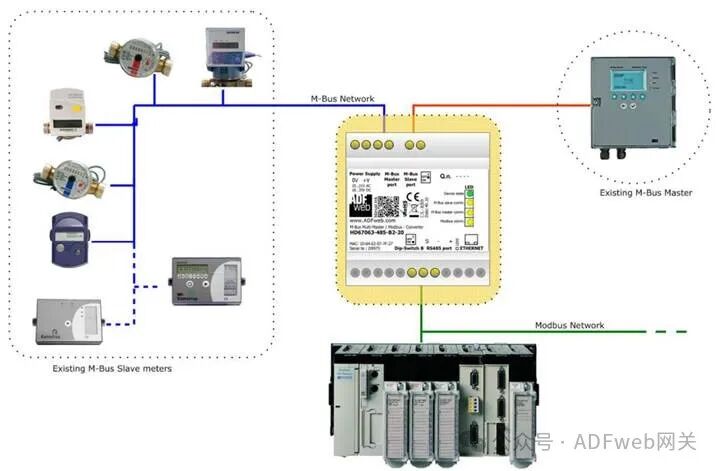
1 Product Features: HD67063-232-B2-xxx / HD67063-485-B2-xxx is a gateway device that supports Modbus slave and M-Bus master/slave communication. It has the following features:
- Electrical isolation between RS232C/RS485 and M-Bus ;
- Baud rate and parity can be changed via software;
- Can be mounted on a DIN rail;
- Power supply range: 15…21V AC or 18…35V DC;
- Operating temperature range: -40°C to 70°C.
This gateway can connect up to 250 standard M-Bus devices, with the specific number of supported devices depending on the model’s xxx number:
- HD67063-232-B2-20 or HD67063-485-B2-20 supports up to 20 M-Bus devices;
- HD67063-232-B2-40 or HD67063-485-B2-40 supports up to 40 M-Bus devices;
- HD67063-232-B2-80 or HD67063-485-B2-80 supports up to 80 M-Bus devices;
- HD67063-232-B2-160 or HD67063-485-B2-160 supports up to 160 M-Bus devices;
- HD67063-232-B2-250 or HD67063-485-B2-250 supports up to 250 M-Bus devices.
2 New Configuration / Open Configuration: The “ New Configuration” button will create a folder containing the entire device configuration. The device configuration can also be imported or exported: To clone the programmable “M-Bus Multi-Master /Modbus Slave Converter” configuration for configuring another device in the same way, the folder and all its contents must be retained; to clone a project for a different version of the project, simply copy the project folder to another name and then open the new folder with the “ Open Configuration” button.
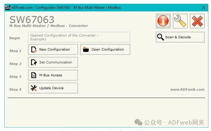
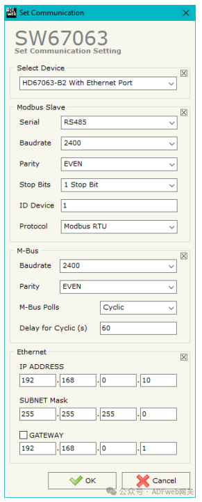
3 Set Communication: By pressing the “ Set Communication” button in the main window (for SW67063, see Figure 2), the “ Set Communication” window (see Figure 3) will appear. This window is divided into two parts. In the “ Hardware Type” section, you can define the hardware used: HD67063-B2 (without Ethernet port); HD67063-B2 (with Ethernet port). The meaning of the “Modbus Slave” field is as follows:
- In the “ Serial Port” field, define the serial port used for Modbus communication (RS232 or RS485);
- In the “ Baud Rate” field, define the data rate for the Modbus line;
- In the “ Parity” field, define the parity method for the Modbus line;
- In the “ Stop Bits” field, define the number of stop bits for the Modbus line;
- In the “ Device ID”” field, define the Modbus ID assigned to the converter. In the “ Protocol” field, you can select the protocol to be used on the Modbus line from the following options:
- Modbus RTU;
- Modbus ASCII;
- JBUS;
- Binary: A simple protocol defined by us, with functionality described in the document “Simple Protocol”, which can be downloaded at:http://www.adfweb.com/download/filefold/Simple_Protocol_ENG.pdf;
- ASCII: A simple protocol defined by us, with functionality described in the document “Simple Protocol”, which can be downloaded at:http://www.adfweb.com/download/filefold/Simple_Protocol_ENG.pdf.
The meaning of the M-Bus field is as follows:
- In the “ Baud Rate” field, the data rate for the M-Bus network is defined;
- In the “ Parity” field, the parity method for the M-Bus line is defined;
- If the “ On-Demand M-Bus Polling” field is checked, the converter will only issue requests when the Modbus registers are requested;
- Otherwise, if the “ Periodic Request” field is checked, the converter will issue requests on the M-Bus network according to the defined delay;
- Otherwise, if the “ Passive Mode” field is checked, the converter will not issue any requests on the M-Bus network, but will wait for existing master devices to complete requests and analyze replies;
- In the “ Periodic Delay (seconds)” field, a time in seconds is defined. This time is used for “ Periodic Request”.
If the “ HD67063-B2 with Ethernet Port” is selected, the “ Ethernet” field means the following (programming port):
- In the “ IP” field, define the IP address to be assigned to the converter;
- In the “ Subnet Mask” field, define the subnet mask to be assigned to the converter;
- In the “ Gateway” field, define the default gateway for the network. This function can be enabled or disabled by checking the checkbox field.
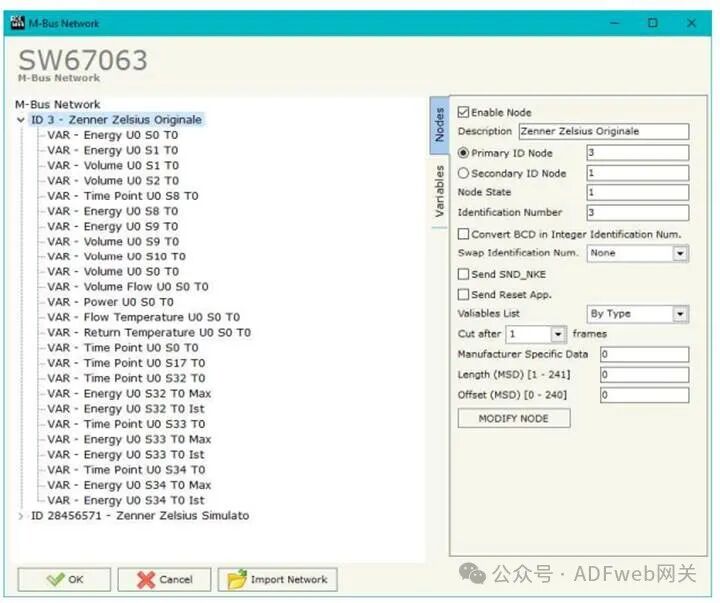
4 M-BUS Access: By clicking the “M-Bus Access” button in the main window (for SW67063, see Figure 2), you can open the “M-Bus Network” window (see Figure 4).
Node Section: To create a new node, you need to select the address type to be used (choose “ Master ID” or “ Slave ID” to initiate a request), then insert the M-Bus device’s “ Master Address” (range from 1 to 250) or “ Slave Address” (range from 0 to 99999999).
In the “ Description” field, you can enter a short description of the node.
In the “ Node Status” field, you can insert a M-Bus device status Modbus address. If this information is not needed, you can set this register to 0.
In the “ Identification Number” field, you can insert a M-Bus device identification number Modbus address. Two consecutive registers need to be read to obtain this value. If this information is not needed, you can set this register to 0.
If the “ Convert BCD to Integer Identification Number” field is checked, the converter will convert the identification number usually represented in BCD format to an integer.
In the “ Swap Identification Number” field, you can select the swap mode for the identification number. If swapping is not needed, you should select “ None”; otherwise, refer to the “ Swap Identification Number” section on page 30 of this document to select the swap mode.
If the “ Send SND_NKE” field is checked, the converter will send the “SND_NKE” frame to initiate communication.
In the “ Send Reset Application” field, if checked, the converter will send the “ Application Reset” command to the slave device.