Introduction to RS-232 Serial Port
Data transmission between computers or between a computer and a terminal typically employs two methods: serial communication and parallel communication. Serial communication is widely adopted due to its lower cost and fewer lines used, especially in remote transmission, which avoids inconsistencies caused by multiple lines. In serial communication, both parties must use a standard interface to facilitate easy connection and communication between different devices.
The RS-232-C interface (also known as EIA RS-232-C) is currently the most commonly used serial communication interface. It was established in 1970 by the Electronic Industries Association (EIA) in collaboration with Bell Systems, modem manufacturers, and computer terminal manufacturers as a standard for serial communication. Its full name is the “Technical Standard for Serial Binary Data Exchange Interface between Data Terminal Equipment (DTE) and Data Communication Equipment (DCE).” Currently, RS-232 is the most widely used serial interface in PCs and the communications industry.
Communication distance: Generally within 13 meters at a baud rate of 9600. Common baud rates include 1200, 2400, 4800, 19200, 38400, etc. The higher the baud rate, the faster the transmission speed, but the stable transmission distance becomes shorter and the anti-interference ability weaker.
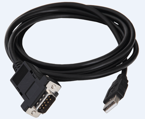
The RS-232 interface is widely used in monitoring and control systems. The RS-232 standard uses a 9-pin or 25-pin D-type connector, with the 9-pin connector being the most common. The interface is shown as follows.
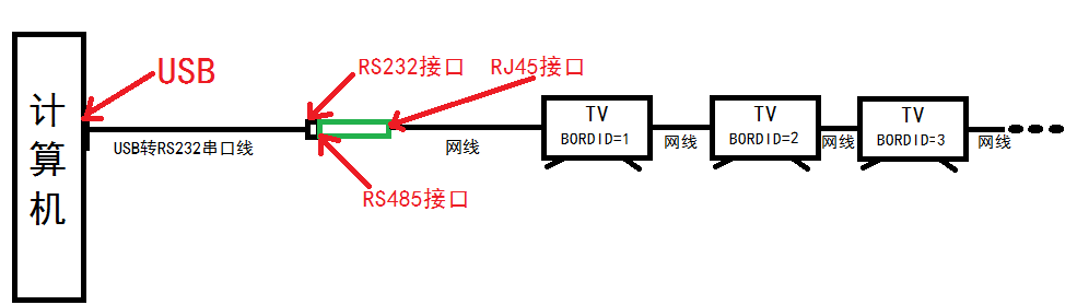
Application Scenario: Subway Station
A computer controls the volume, brightness, contrast, and source switching of the platform display screen.
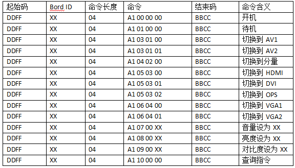
Computer Control Command Specification
The serial port command consists of three parts: start code, command code, and end code. The start code indicates the beginning of the command, while the end code indicates the termination of a serial port command. The command code includes BordID, command length, and command composition. BordID is the address code for the terminal receiving the serial command, which ranges from 00-FF (i.e., integers from 0-255). If the address code is 00, it indicates that this command is a system broadcast, and all terminals connected to the system will respond to the serial command; if it is another value, it indicates that the serial command is only for the current address, and only the terminal with the same address code will receive the command.
PC → Bord ID Control Command
For example, if Bord ID 3 (monitor 3, which could also be 4, 5, 6, or N…) receives a command from the computer, it will return the same command, with the return command’s start code being ABAB and the end code being CDCD. If we want to send a command to switch to channel HDMI, we perform the following operation:
Bord ID 3 received:

Bord ID 3 returns:

The computer → Bord ID control command where XX represents the corresponding hexadecimal value for volume, brightness, contrast, etc. If XX exceeds the upper limit for volume, brightness, or contrast (maximum value is 100 in decimal, which corresponds to 64 in hexadecimal), the command will not be executed.
General Software Design
Setting Bord ID
If you need to use the serial port function of Bord ID (i.e., the device), you need to set the serial port switch to ON. After setting, generally, you need to power cycle the entire machine and reset the environment variables to respond to serial commands; Bord ID is generally modified on the TV side (i.e., terminal device), and the default is 1, which can be selected from 1-255. Of course, depending on the application product, users can set it according to the supported range.
Command Return
a. The monitor can respond to remote control and button operations in standby or power-on state, but should not generate a return of serial commands;
b. For serial commands with a specified Bord ID, the serial port must return a command indicating that the command has been completed after execution;
c. For broadcast serial commands, no command return should be generated;
d. In standby state, when sending a power-on command, the PM port receives the command and executes it, but can only relay the received serial power-on command parameters, and cannot indicate whether it is a broadcast power-on or an address-specific power-on. Therefore, after the monitor completes the power-on, the system software will return a power-on command return;
Commands that can respond in standby
Bord ID can respond to commands in standby mode, including query commands and power-on commands; other commands will not respond. In standby mode, the main chip’s PM port receives and responds to commands. It is required that in standby mode, it can only correctly identify and accurately judge, without misoperation.
1) Query command: DD FF XX 04 A1 10 00 00 BB CC (where XX is the overall Bord ID)
Return command format: AB AB XX 04 A1 FF FF FF CD CD
Explanation: The XX in the command corresponds to the Bord ID of the query command, the first FF is meaningless, the second FF is the power-on or standby status bit, and the third is the volume bit.
2) Power-on command: DD FF XX 04 A1 00 00 00 BB CC
Return command format: AB AB XX 04 A1 00 00 00 CD CD
Explanation: When the Bord ID power-on action is completed and can respond to subsequent serial commands, the system software returns the second return command, notifying the control side that the TV is ready to receive and can normally execute serial commands.
Commands that can be received during power-on
1) Query command: DD FF XX 04 A1 10 00 00 BB CC
Return command format: AB AB XX 04 A1 FF FF YY CD CD
2) Standby command: DD FF XX 04 A1 10 00 00 BB CC
Return command format: AB AB XX 04 A1 01 00 00 CD CD
3) Signal source switch command: DD FF XX 04 A1 XX XX XX BB CC (where the first XX is the overall Bord ID, and the following three XX are the command to switch the signal source, which can refer to the previous protocol)
4) Volume, brightness, contrast setting command: DD FF XX 04 A1 XX XX XX BB CC (where the first XX is the overall Bord ID, and the following three XX are the commands to set volume, brightness, or contrast, as detailed in the above protocol)
Tool Usage
There are various serial port tools available on the market for RS232, such as SecureCRT_x86, SUDT AccessPort, etc. We are using SSCOM32.exe.
PC Control Tool: SSCOM32.exe
Tool settings are as follows:
Baud Rate: 9600
Data Bits: 8
Stop Bits: 1
Parity: None
HEX Display: Checked
HEX Send: Checked
Serial Port Number: COM port recognized by USB to RS232 serial cable
Serial Port Status: Open Serial Port (shows “Close Serial Port” after opening)
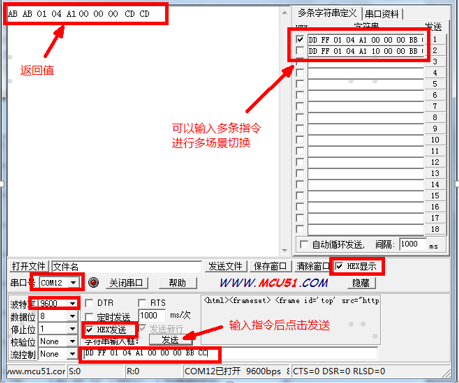
Now, with the serial port connected at the hardware level, following the above operations will allow a PC to control the device.

3~5.5V, High-Speed 10 Mbps Half-Duplex Low-Power 485 Transceiver
TP75176E
TP75176E is a low-power, differential line RS485 transceiver powered by a single supply of 3.0~5.5 V. This device features low power consumption and shutdown mode, making it ideal for power-sensitive applications.
The transmission rate of TP75176E can reach up to 10 Mbps. Up to 32 transceivers can be connected on the bus. The thermal shutdown circuit can prevent excessive power consumption caused by bus contention or output short circuits. Under fault conditions, if the internal driver circuit detects a significant temperature rise, the thermal shutdown circuit will force the driver output into a high-impedance state. If the input is unconnected (floating) or shorted, the receiver’s fail-safe feature will keep the output at a logic high state. The rated temperature range for this device is -40° C to +125° C. TP75176E is available in 8-pin SOIC and DFN packages.
● Powered by a single supply of 3~5.5V
● Complies with EIA RS 485/RS-422 standards across the entire common mode range
● Data rate options: 10 Mbps
● Half-duplex
● Up to 32 transceivers can be connected on one bus
● Rated temperature range: -40° C to +125° C
● Available in 8-pin SOIC and DFN packages
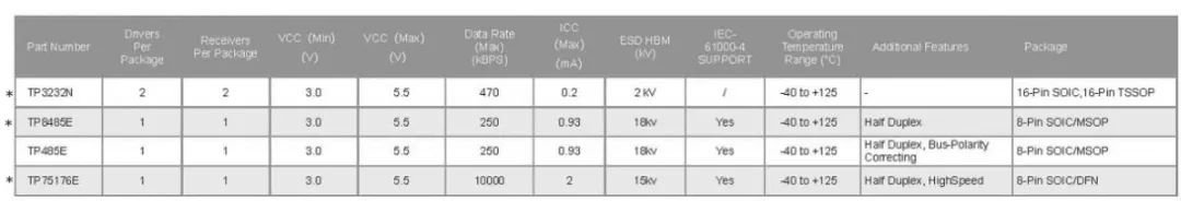
RS-232, RS485 Transceiver Selection Guide

SiRuPu is a semiconductor company funded by a well-known VC in Silicon Valley, focusing on high-speed, high-precision, low-power, and ultra-low-noise analog chips and system products. It has independent intellectual property rights and continuous innovation, aiming to provide high-performance, high-reliability, and cost-effective analog chips for the market and customers. Its products cover various application fields including industrial, medical devices, automotive electronics, communication systems, and information security.
First-class design expertise, precision analog design teams, and continuous development are the core values upheld and relied upon by SiRuPu. SiRuPu holds dozens of analog patent technologies and maintains continuous innovation, with its senior analog technology team consisting of many Ph.D. holders from top American companies, each with over twenty years of experience focused on analog design and rich experience in high-end chip design and management.
Excellent performance is ensured by international first-class analog foundries located in Israel and the United States, meticulous chip design, and rigorous testing techniques, guaranteeing high performance, high integration, high stability, and powerful functionality of SiRuPu’s analog products. From ADCs, DACs, to amplifiers, our designers are dedicated to refining every specification and detail; simultaneously, the “3PEAK Laboratory” pursues the best testing techniques for every analog performance and explores extreme application environments, such as conducting comprehensive testing and research on the nV-level noise characteristics of “ultra-low noise analog chips” in both time and frequency domains.
Outstanding quality is ensured by a strict and comprehensive quality assurance system established based on the highest industry standards, ensuring that every product undergoes dozens of rigorous inspection tests, achieving world-class product consistency and reliability. “3PEAK Laboratory” reliability tests include HTOL high-temperature operating life tests, HAST high-temperature high-humidity accelerated pressure tests, TCT temperature cycling tests, ESD testing, and more.
Stable supply SiRuPu challenges the conventional supply cycle of the industry through binding cooperative relationships with suppliers. In wafer processing, SiRuPu is the largest customer of TowerJazz in China, having established a strategic partnership in 2012, ensuring the best speed from wafer processing to mass production, reaching customers in the shortest time. Meanwhile, through years of collaboration with various foundries, they have become fully familiar with SiRuPu’s product processes, ensuring smooth and stable production, with factory management expressing great confidence and support for SiRuPu’s products.
For more details, please contact:

China’s Leading Semiconductor Agent and Solution Design Provider
Da Sheng Tang Electronics Co., Ltd.
(Shenzhen, Guangzhou, Beijing, Shanghai, Xi’an, Suzhou, Hong Kong)
Hotline: 400-662-1-662
Da Sheng Tang Electronics

Scan the QR code | Follow us
WeChat ID | Da Sheng Tang Electronics