 When designing automation equipment, we often need to monitor and control various pressure sensors, instrument signals, or temperature sensors. Many of these instruments will have analog input or output signals, and we need to use PLCs to read these analog signals and output analog signals to the instruments. What exactly is an analog signal? Some electrical engineers often miscalculate during debugging; it is not as complicated as it seems. Let’s take a look at some common scenarios for using analog signals.1. Common Analog Signal RangesAnalog Input: DC -10V to +10VDC, -20mA to +20mA, DC 0V to 10VDC, 4mA to 20mAAnalog Output: DC -10V to +10V, 0mA to 20mA, DC 0V to 10V, 4mA to 20mAThere are also DC 0V~5V, etc., but we will mainly discuss 0~10V and 4~20mA.2. Usage Scenarios: Where are they used?
- Frequency Converter Control
- Temperature Monitoring
- Pressure Monitoring
- Level Monitoring
- Proportional Valve Control
- …………
There are many places where analog signals are used, with the most common being frequency converters, pressure, and level monitoring. In recent years, with the development of technology, communication methods may be more commonly used, and we may not need to use these analog signals, but we must understand them.3. Choosing the Type of Analog Signal: Voltage or Current? How to ChooseBefore selecting a signal, it is essential to understand the fundamental differences; otherwise, you may end up debugging late into the night.0-10V Voltage Signal: Like “short-distance express delivery,” suitable for devices within 10 meters, such as PLCs and frequency converters in the same cabinet, or temperature sensors within the cabinet. The advantage is simple wiring (just two wires), which beginners can handle; however, the downside is significant: the longer the wire, the more susceptible it is to interference (for example, if there are power lines from nearby frequency converters), and the signal will “attenuate” (for instance, a 10V signal transmitted over 20 meters may only remain at 8V, leading to inaccurate data).4-20mA Current Signal: This is like a “long-distance truck,” stable over distances of 50 meters or even 100 meters, such as level transmitters in the corner of a workshop or outdoor flow meters. It has strong anti-interference capabilities and can perform “self-checks”: under normal conditions, the signal will not drop below 4mA. If the PLC reads 0mA, there is no need to check the sensor; first, check if the wire is broken (0-10V cannot distinguish between “no signal” and “value is 0”).4. Converting Analog Signals to Desired Data.Below, we will use a thermometer and a proportional valve as examples.Analog Input:The external thermometer outputs a DC 0~10V analog signal, which is connected to the PLC’s analog input module. The PLC analog input produces a value (e.g., 0~32000), and we then convert this value to voltage, allowing us to know the external input voltage.Let’s look at the diagram; this should be easy to understand.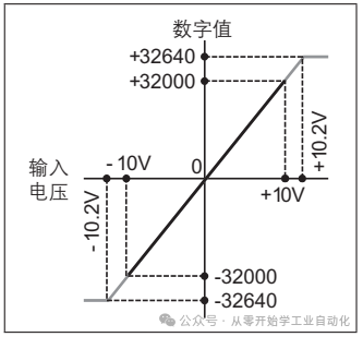 Then, in our program, we convert the value, for example, 0~10V corresponds to 0~100 degrees Celsius. Generally, there is a conversion formula for voltage to temperature. We substitute the voltage value calculated by the PLC into the formula to obtain the desired temperature.Calculation 1: First, calculate the voltage obtained from the analog input module in our program.Let y be the value and x be the voltage. The formula is y=ax+b.Substituting:32000 = a * 10 + b0 = a * 0 + bWe derive the formula: y=3200x, x=y/3200 (remember this, it will be used later).Calculation 2: Calculate the temperature corresponding to the voltage.Let 0 degrees Celsius correspond to 0V, and 100 degrees Celsius correspond to 10V, which also forms a linear equation relationship y=ax+b. Here, y is temperature and x is voltage.0 = a * 0 + b100 = a* 10 + bWe derive the formula: y = 10x.Analog Output:We need to control a proportional valve (a device that can control output pressure, which is not commonly used, and I have less exposure to it). This proportional valve can receive a current of 0~20mA, corresponding to an output pressure of 0~500KPa.As shown in the figure:
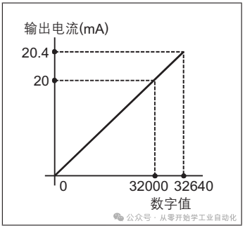 In our program, we write the corresponding value to the register, writing 32000 corresponds to 20mA, at which point the proportional valve will output 500KPa pressure, and writing 0 corresponds to 0mA, resulting in 0KPa pressure from the proportional valve.Calculation 1: First, convert our corresponding value 0~32000 to 0~20mA.Let y be the current and x be the value.The formula is also y=ax+b.20 = a * 32000 + b0 = a * 0 + bWe derive the formula:y= x/1600.Calculation 2: Convert 0~20mA to 0~500kPa.Let y be pressure and x be current.The formula is also y=ax+b.0 = a * 0 +b500 = a * 20 +bWe derive the formula:y= 25x.5. Programming Example: We will use FX3U’s 4AD and 4DA as examples.
Here, let’s talk about the buffer operation instructions FROM/TO and U/G instructions; they serve the same purpose: moving data.
TO:Module number, buffer#, data to be transmitted, number of lengths
FROM:Module number, buffer#, where to store the read data, number of lengths
U/G:U module number, G buffer. Use MOV or BMOV instructions.
Let’s start programming.
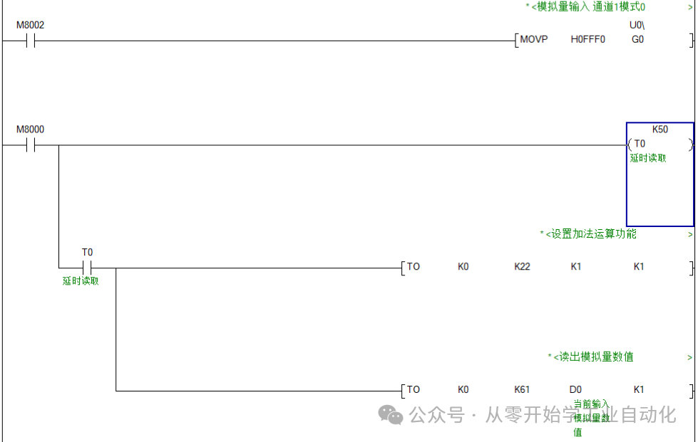
Analog Input Module FX3U-4AD Programming:BFM #0 Input Mode:Select which type of analog signal; for the fourth point, we choose the DC 0~10V voltage analog signal from the thermometer, so the mode can be selected as 0.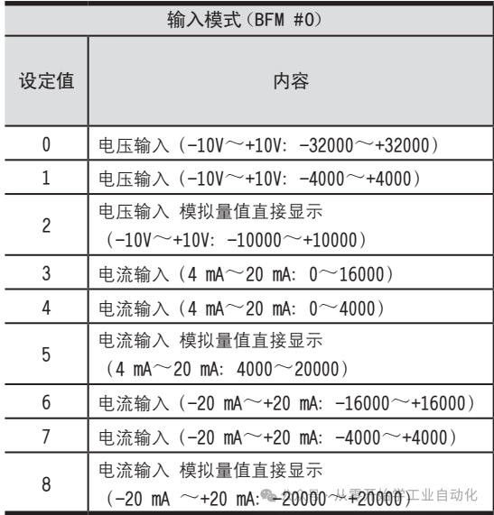 BFM #22 Set Data Addition Function:
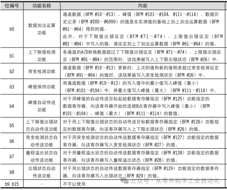 BFM 61# Read Values from Buffer:In channel data (BFM #10~#13), peak values (BFM #101~#104, #111~#114), and historical data (BFM #200~#69999), add the addition operation data (BFM #61~#64), and the value of this addition operation data is stored in 61#.Note: When using addition operation data, the addition operation data function (BFM#222b0) must be set to ON.
PLC Program: (From the derived formula: Voltage x = Value y/3200; Temperaturey = 10 * Voltage x)
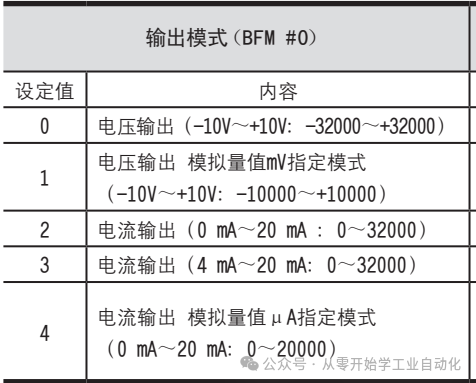
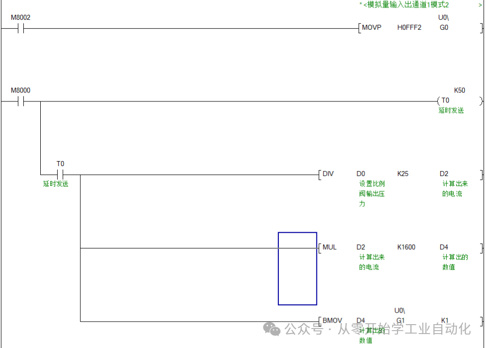
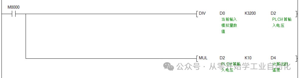 OK, D4 is our temperature.Analog Output Module FX3U-4DA Programming:BFM #0 Output Mode:First, determine the output mode, select which type of analog signal. For the fourth point, we choose the 0~20mA current analog signal for the proportional valve, so the mode is selected as 2.
 BFM #1 Output Data:
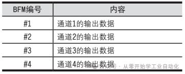 Output is slightly simpler than input.PLC Program: (From the derived formula: Current y =Value x/1600; Pressurey=25* Current x)We need to calculate the value and store it in the PLC buffer.Current x = Pressure y / 25, Value x = Current y * 1600.
 OK, we have completed it. Isn’t it simple?Summary of Three Key Points:
- Understand the buffer function.
- Familiarize yourself with FROM/TO and U/G operation instructions.
- Understand the conversion formulas between PLC data values, analog voltage/current, and actual temperature/pressure.Once you grasp these three points, it becomes very easy.
If you find this useful, please help by following and saving it.
Here are some related technical sharing articles; feel free to check them out:
3-Minute Solutions for Common Connection Methods between C# Winforms and Customer Factory MES (Including Programming Details)
Beginner Project: [Automatic Screw Machine] C#, PLC, Touch Screen Practical (1/5): Electrical Preliminary Design