1. Features
Ultra-compact, ultra-thin PicoStar™ package, dimensions: 0.55 × 0.61 × 0.24mm
Power supply voltage range: 1.4V to 5.5V
16-bit resolution: 0.0078125°C (LSB)
1.4μA average current, 1Hz conversion period – sleep current 65nA
I2C interface
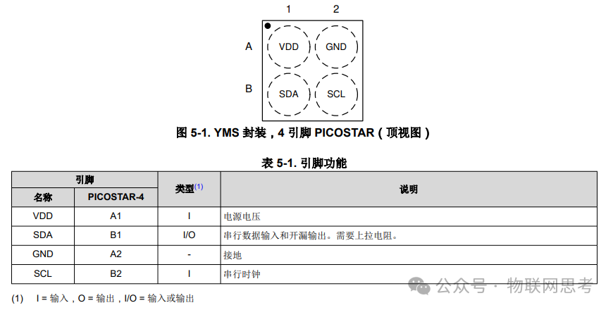
2. Pins and Package
3. I2C Address
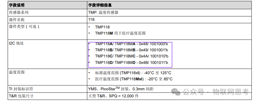
The TMP118 has different suffixes with different addresses. This test is for TMP118B, so the I2C address is 0x49.
4. Register Description
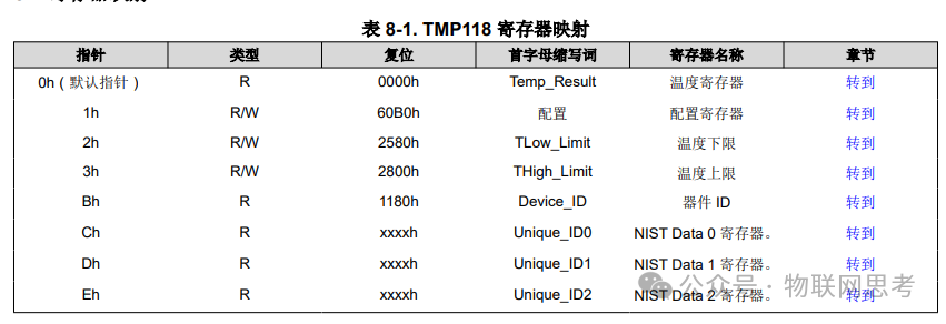
The registers are also very concise, with only 8 registers. The main ones to focus on are the temperature register (0h), configuration register (1h), and device ID register (Bh).

The data read is a digital value, multiplied by 0.0078125 to get the actual measured temperature.
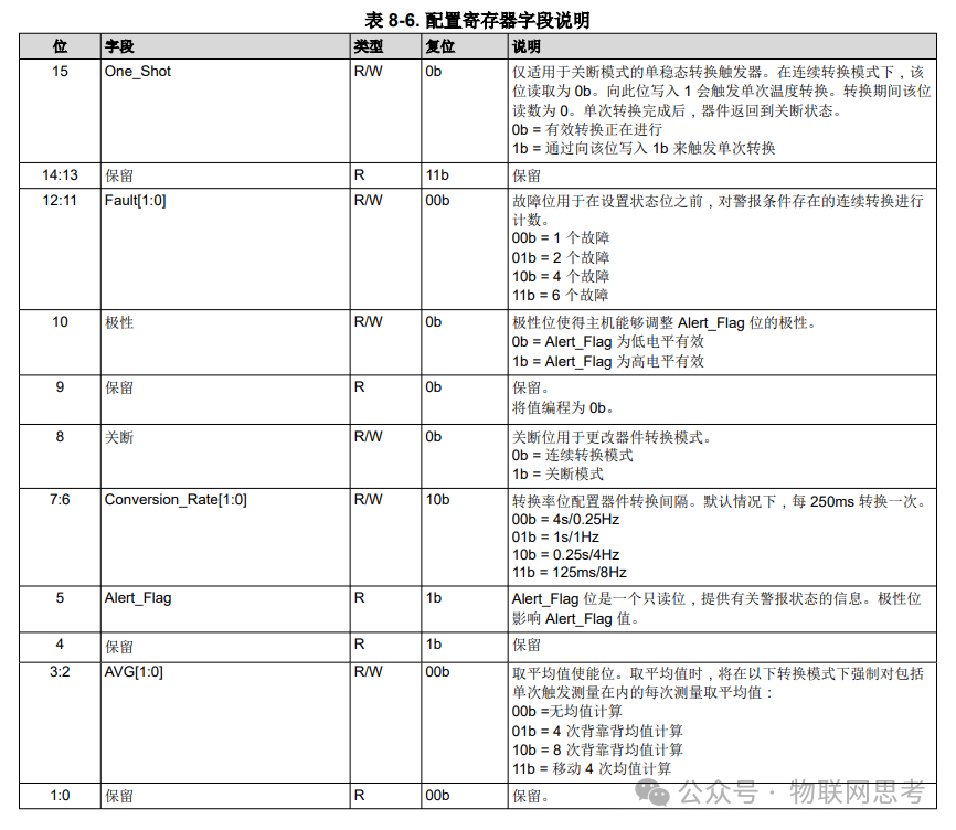
The configuration register mainly configures the conversion rate, average enable bit, etc. The default configuration can also be used.

The device ID is 0x1180, which can be used to check if the device is online and verify the I2C communication timing.
5. Core Code
The definitions for registers, I2C address, device ID, etc., are as follows:
#define TMP118_I2C_BUS        1 /* I2C bus */

#define TMP118_I2C_ADDR       0x49      /* TMP118B 0x49 */
#define TMP118_DEV_ID         0x1180    /* Device ID */
#define TMP118_LSB_VAL        0.0078125 /* Resolution */

#define TMP118_REG_RES        0x00 /* Result register */
#define TMP118_REG_CONF       0x01 /* Configuration register */
#define TMP118_REG_LOW_LIMIT  0x02 /* Lower limit register */
#define TMP118_REG_HIGH_LIMIT 0x03 /* Upper limit register */
#define TMP118_REG_DEV_ID     0x0B /* ID register */

#define TMP118_REG_UNQ_ID0    0x0C /* Unique ID register 0 */
#define TMP118_REG_UNQ_ID1    0x0D /* Unique ID register 1 */
#define TMP118_REG_UNQ_ID2    0x0E /* Unique ID register 2 */

/* TMP118_REG_CONF */
#define TMP118_ONE_SHOT       (1 << 15) /* One-shot trigger */

/* Fault count */
/* 0: 1 fault
   1: 2 faults
   2: 4 faults
   3: 6 faults
*/
#define TMP118_FAULT_CNT(x)   (((x) & 0x3) << 11)

#define TMP118_ALERT_POLARITY (1 << 9) /* Active high polarity */
#define TMP118_SHUT_DOWN      (1 << 8) /* Shutdown mode */

/* Conversion rate */
/* 0: 0.25HZ
   1: 1HZ
   2: 4HZ
   3: 8HZ
*/
#define TMP118_CON_RATE(x)    (((x) & 0x3) << 6)

/* Average enable bit */
/* 0: No averaging
   1: 4 times
   2: 8 times
   3: Moving average 4 times
*/
#define TMP118_AVE_CNT(x)     (((x) & 0x3) << 2)
The read and write functions are implemented as follows:
// Read TMP118
static int tmp118_read(int bus, uint8_t reg, void *buff, int len) {
    int ret;

    /* Start transmission */
    si2c_start(bus);

    /* Select device address for write operation */
    if (si2c_select(bus, TMP118_I2C_ADDR, SI2C_OP_WRITE) != 0) {
        si2c_stop(bus);
        return 0;
    }

    /* Write device address */
    if (si2c_tx(bus, ®, sizeof(reg)) != sizeof(reg)) {
        si2c_stop(bus);
        return 0;
    }

    /* Start transmission */
    si2c_start(bus);

    /* Select device address for read operation */
    if (si2c_select(bus, TMP118_I2C_ADDR, SI2C_OP_READ) != 0) {
        si2c_stop(bus);
        return 0;
    }

    /* Receive data */
    ret = si2c_rx(bus, buff, len);

    /* Stop transmission */
    si2c_stop(bus);

    return ret;
}

// Write TMP118
static int tmp118_write(int bus, uint8_t reg, void *buff, int len) {
    int ret;

    /* Start transmission */
    si2c_start(bus);

    /* Select device address for write operation */
    if (si2c_select(bus, TMP118_I2C_ADDR, SI2C_OP_WRITE) != 0) {
        si2c_stop(bus);
        return 0;
    }

    /* Write register address */
    if (si2c_tx(bus, ®, sizeof(reg)) != sizeof(reg)) {
        si2c_stop(bus);
        return 0;
    }

    /* Write data */
    ret = si2c_tx(bus, buff, len);

    /* Stop transmission */
    si2c_stop(bus);

    return ret;
}
Read device ID:
static int tmp118_read_id(int bus) {
	uint8_t val_8[2];
    uint16_t val_16;

    tmp118_read(bus, TMP118_REG_DEV_ID, (uint8_t *)&val_8, 2);
	val_16=(val_8[0] << 8) + val_8[1];
    if (val_16  != TMP118_DEV_ID) {
        return -1;
    }
    return 0;
}
Reset TMP118:
static void tmp118_reset(int bus) {
    uint8_t val[2];

    val[0] = 0x00;
    val[1] = 0x06;

    si2c_start(bus);
    si2c_tx(bus, val, sizeof(val));
    si2c_stop(bus);
}
Read temperature, can be called periodically:
void tmp118_temp_read(void) {
    int8_t val[2];
    int    bus = TMP118_I2C_BUS;
    float temp;

    tmp118_read(bus, TMP118_REG_RES, (uint8_t *)&val, 2);
    temp = ((val[0] << 8) + val[1]) * TMP118_LSB_VAL;
	dbg_info("  %0.2f", temp);
}
Initialization:
 void tmp118_init(void) {
    uint8_t  val_8[2];
    uint16_t val_16 = 0;
    int      bus    = TMP118_DEV_START;

     si2c_init(bus); // I2C interface initialization

     tmp118_reset(bus);
     delay_ms(10);

     if (tmp118_read_id(bus)) {
		dbg_info("tmp118B %d err \r\n", bus);
        return;
     }

     tmp118_read(bus, TMP118_REG_CONF, &val_8, 2);
     val_16 = (val_8[0] << 8) + val_8[1];
     val_16 |= TMP118_CON_RATE(3); // Configure conversion rate
     val_8[0] = (val_16 >> 8) & 0xff;
     val_8[1] = (val_16 >> 0) & 0xff;
     tmp118_write(bus, TMP118_REG_CONF, &val_8, 2);
}
6. I2C Driver
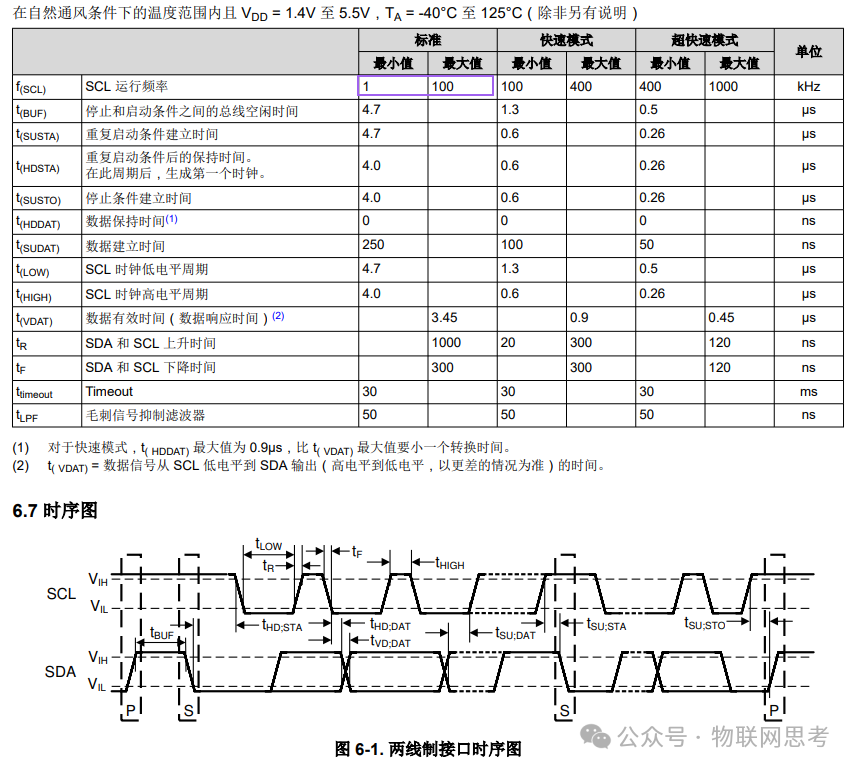
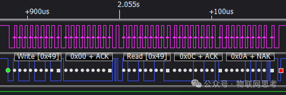
It can be seen that the TMP118 does not have high timing requirements, supporting rates from 1kHz to 100kHz in standard I2C mode. Therefore, this article uses software to simulate I2C, capturing the timing as follows:
7. Phenomena
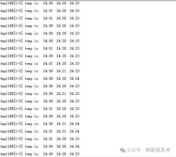
During actual testing, three TMP118 sensors were connected, and the temperature measurement outputs were as follows:
 ——————END——————