Today, comrades, we are going to disassemble a sensor used in mining.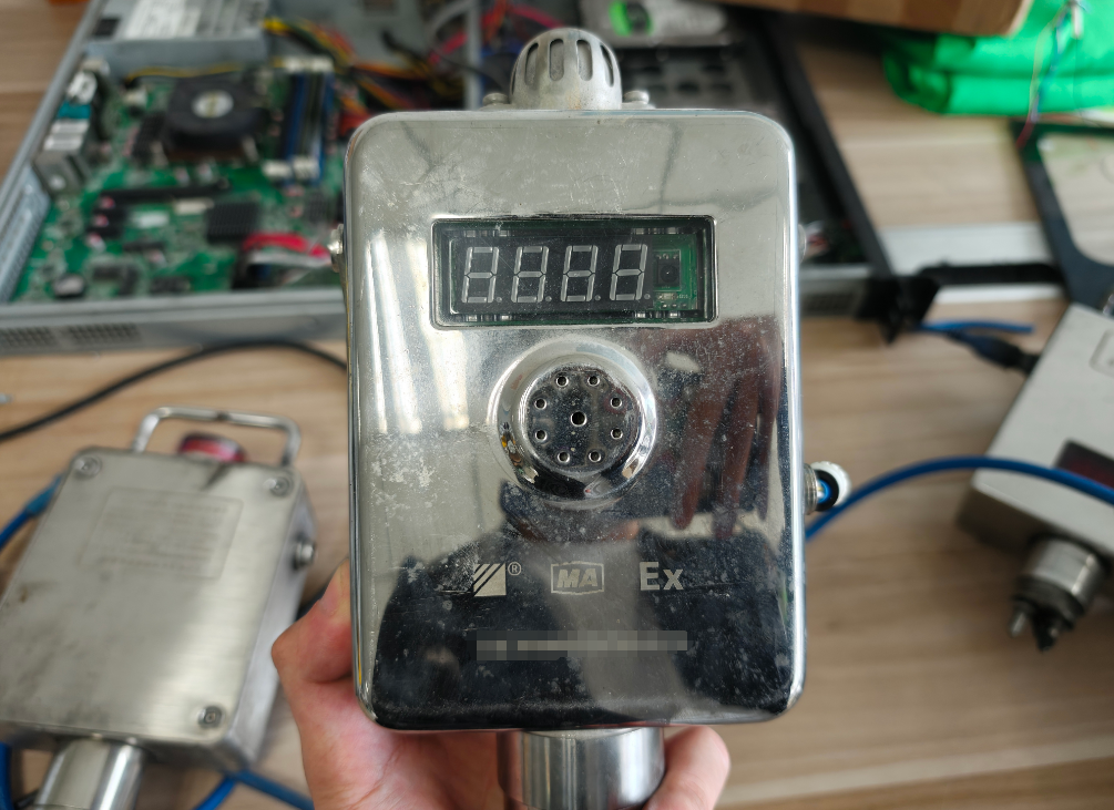 It feels heavy and substantial in hand.After all, it is meant to be used underground, where the environment is harsh.
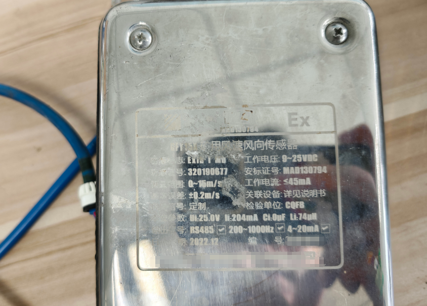 This is a sensor for detecting wind speed and direction. You can tell it has weathered many storms; the back is already quite worn, and this is after I cleaned it.
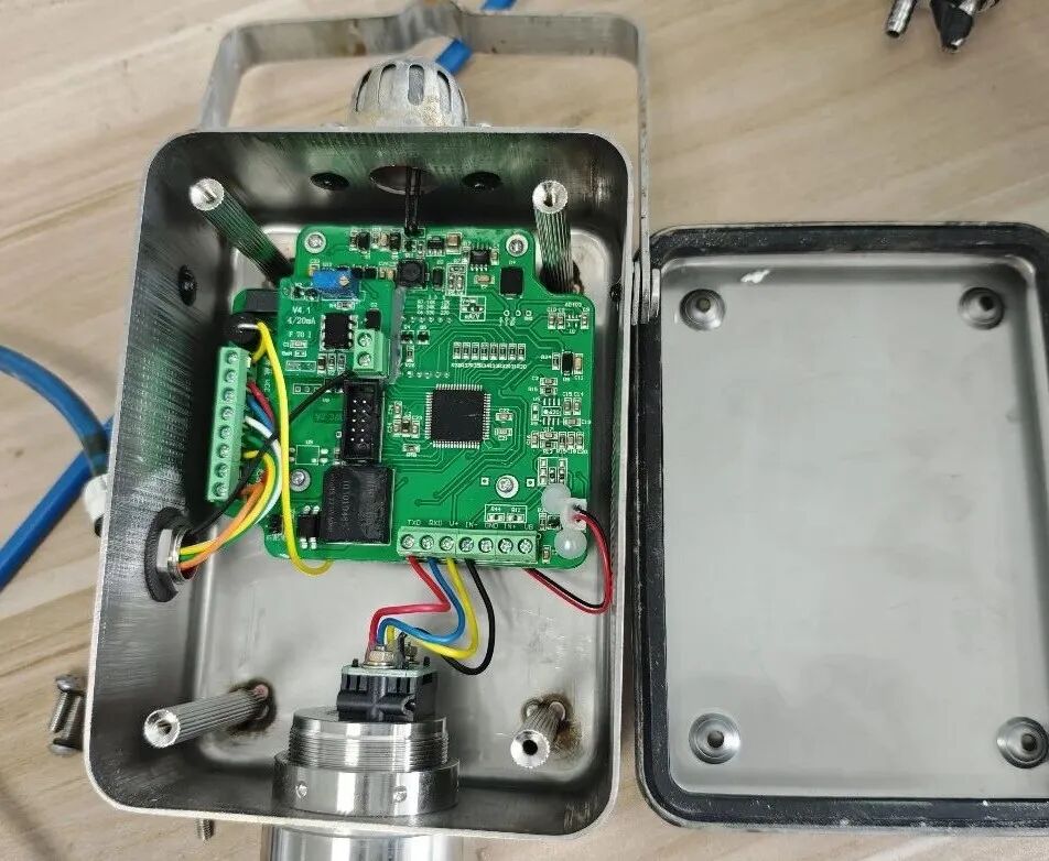 Upon opening it, I found that the inside is quite simple.In fact, a large part of it is empty.
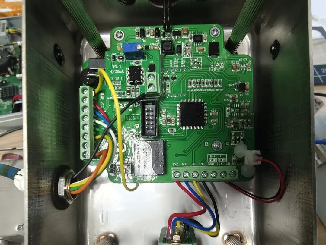 The circuit board is coated with a layer of conformal coating (I assume), which made my hands sticky.
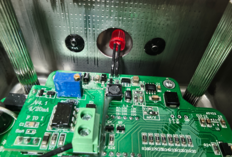 There is a large LED connected to the board as an indicator light, very plain and simple.
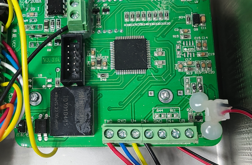 In the lower right corner, there are a bunch of terminal blocks.However, they are not all connected, possibly different models connect to different wires.But GND is not connected???
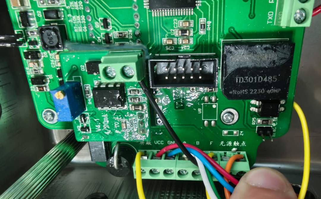 Another side of the terminal blocks.There are three labeled A, B, and F; I don’t understand what they are. Does anyone knowledgeable have insights?
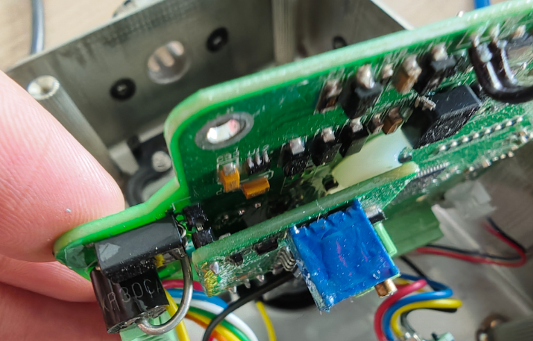 A small circuit board is also connected to the main board, positioned by pin headers???
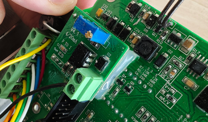 Then it is fixed with a white sticky adhesive.This small board seems to be for adjusting precision?
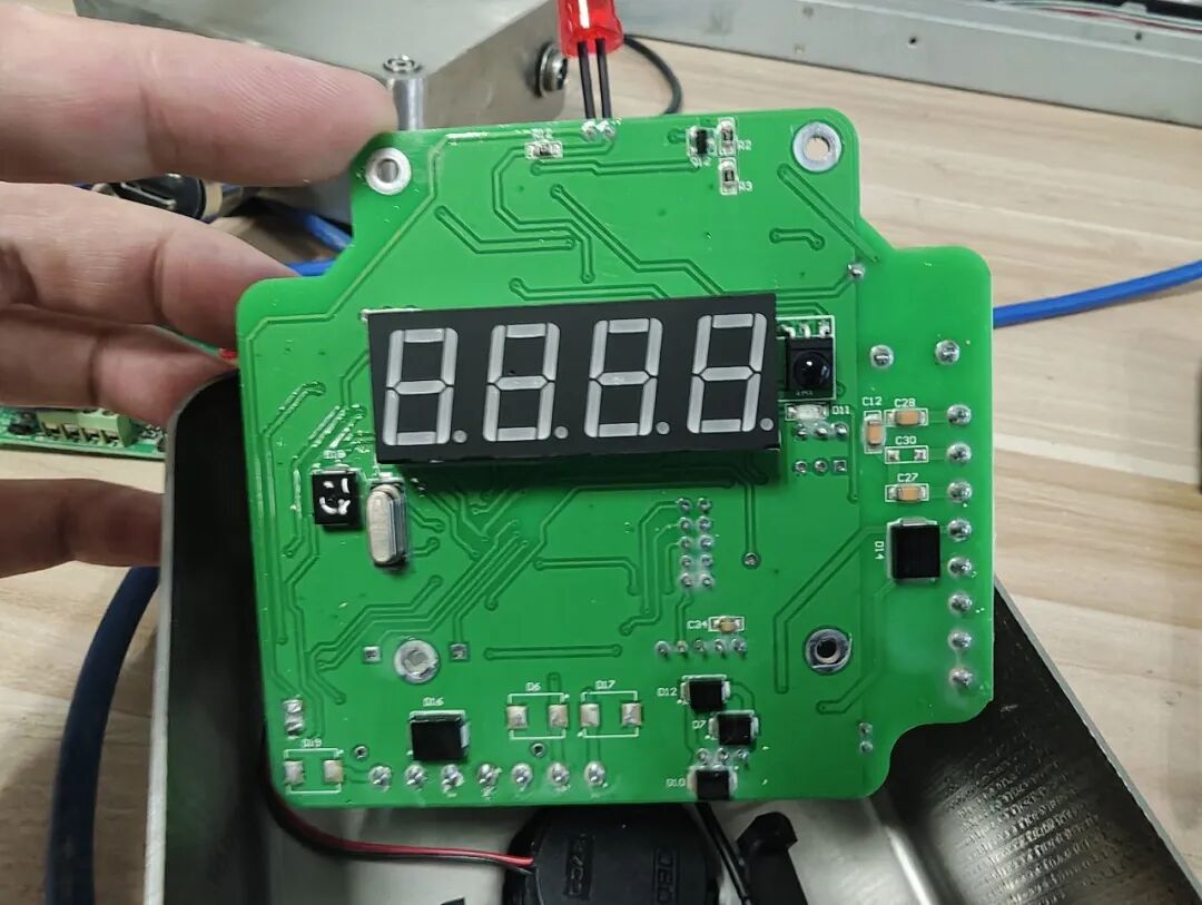 The back of the main board has a digital tube and some scattered components; there isn’t much else.
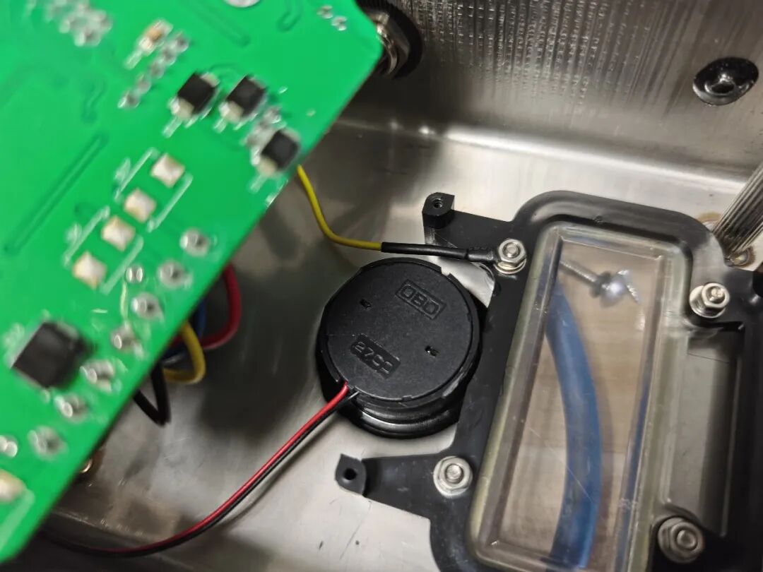 The sensor itself is also on the back of the board, which is hard to access, so I just took a photo from the outside.Then I noticed that the “shielding” yellow wire on the terminal block is connected to the casing.This is what the device looks like; although it is for mining, it doesn’t seem particularly special, just that the wiring is quite thick.