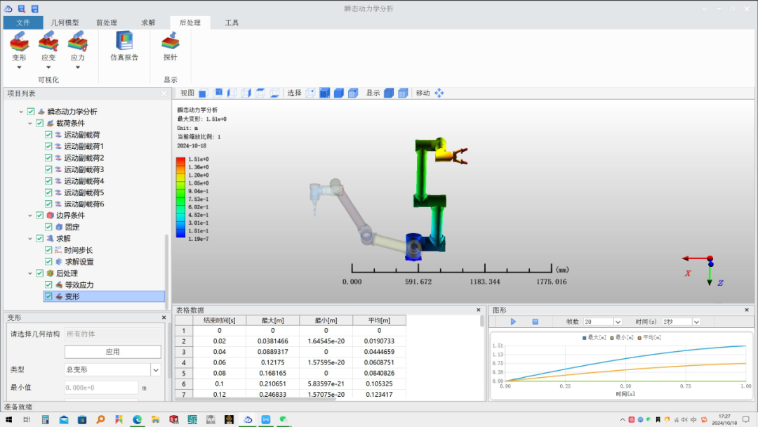
This case is based on the domestic Yuhai ParaCS software for transient dynamics analysis, software version V4.8.0;
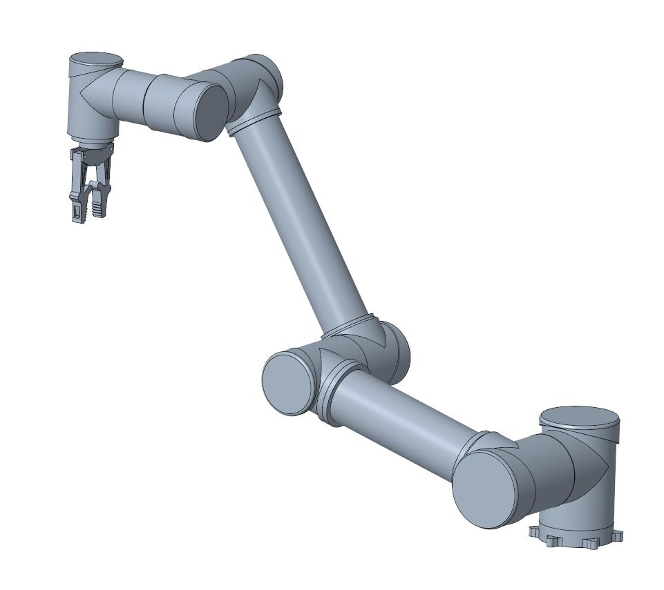
The model of the serial collaborative robot is shown in the figure below, which simplifies the internal electrical structure;
1

Start the Yuhai ParaCS software by double-clicking the icon to open it

2

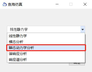
Select the transient dynamics module from the module selection interface to enter the software interface
3

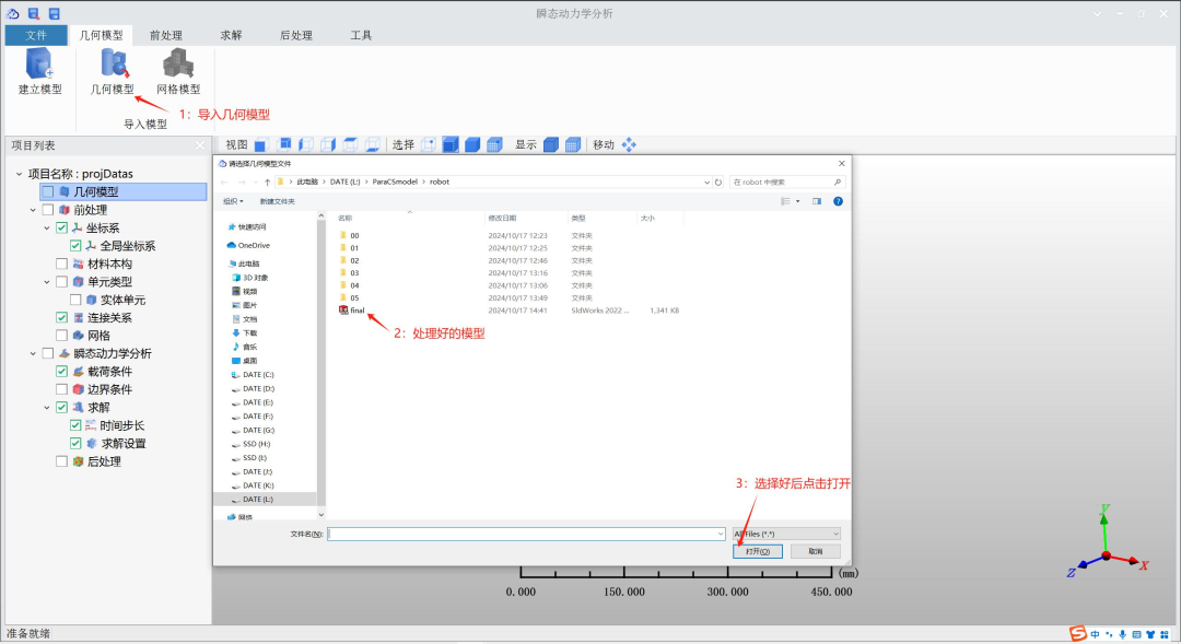
Enter the software interface to import the model
4

After completing the model import, create material properties
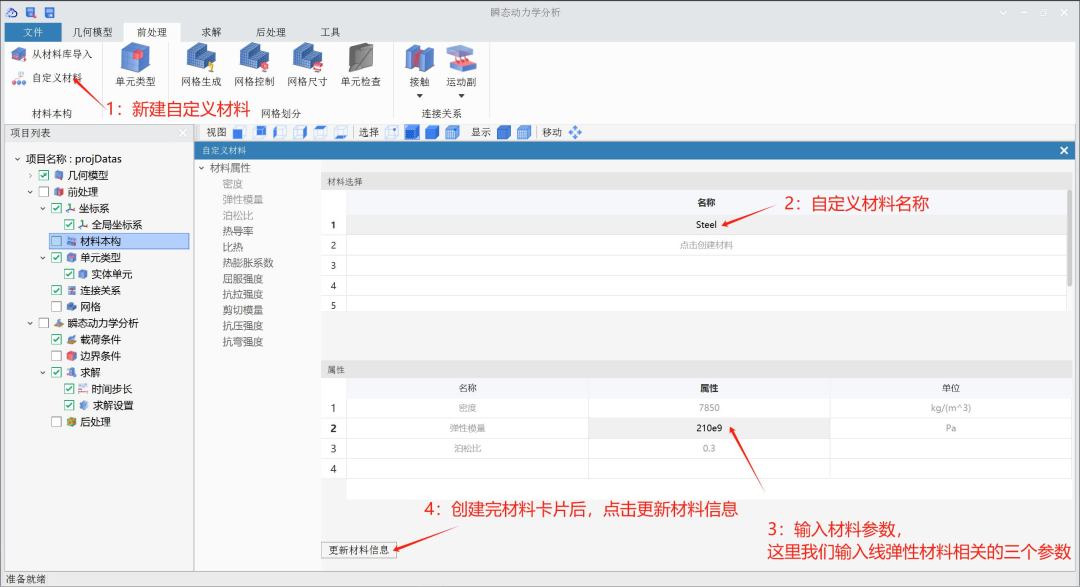
5

Mesh division of the structure
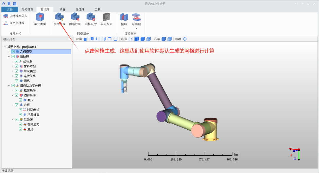
The divided mesh is shown in the figure below:
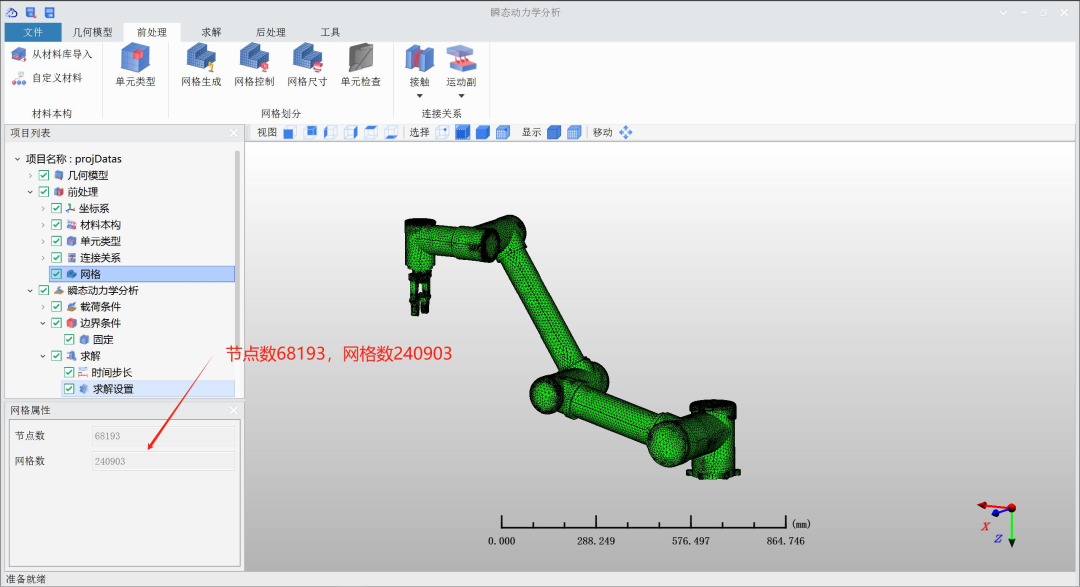
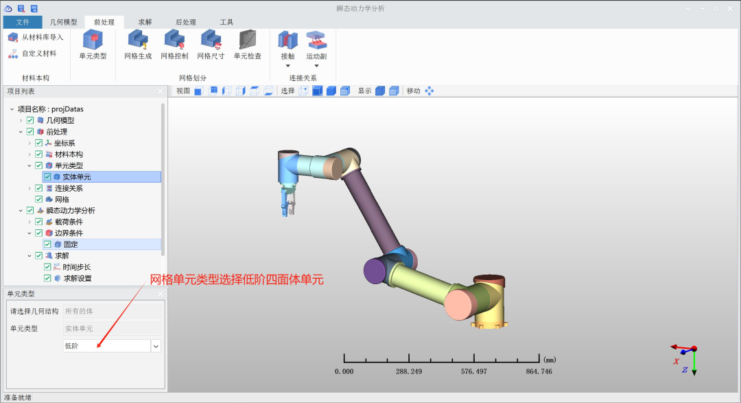
The mesh element type is tetrahedral low-order elements
6

Building the connection relationships of the model
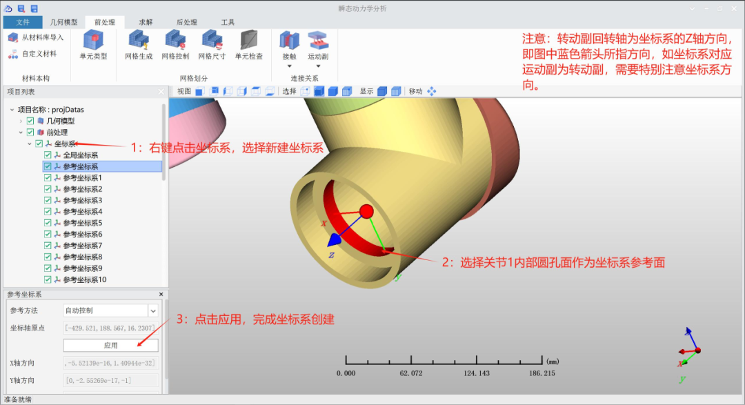
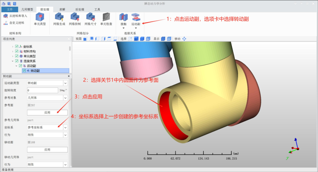
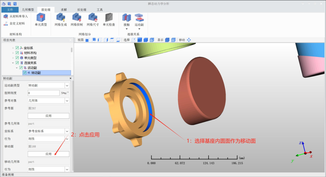
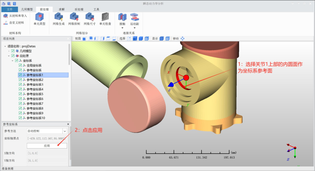
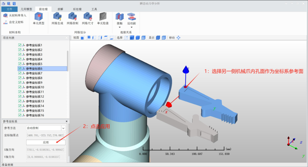
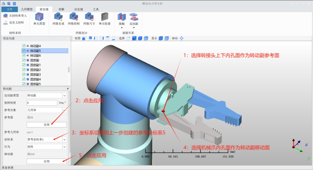
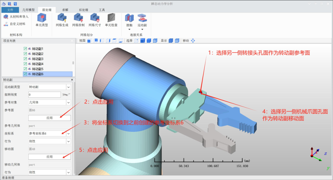
The rotational pairs require their corresponding reference coordinate systems to ensure correct subsequent solutions. Both the motion pairs and their corresponding reference coordinate systems can be established simultaneously.
6.1 Establishing the rotational pair between Joint 1 and the base
6.2 Establishing the rotational pair between Joint 1 and Joint 2
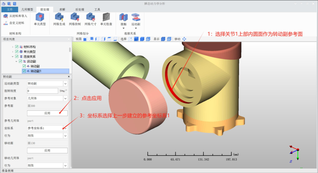
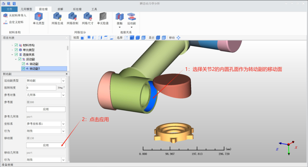
6.3 Establishing the rotational pair between Joint 3 and Joint 4
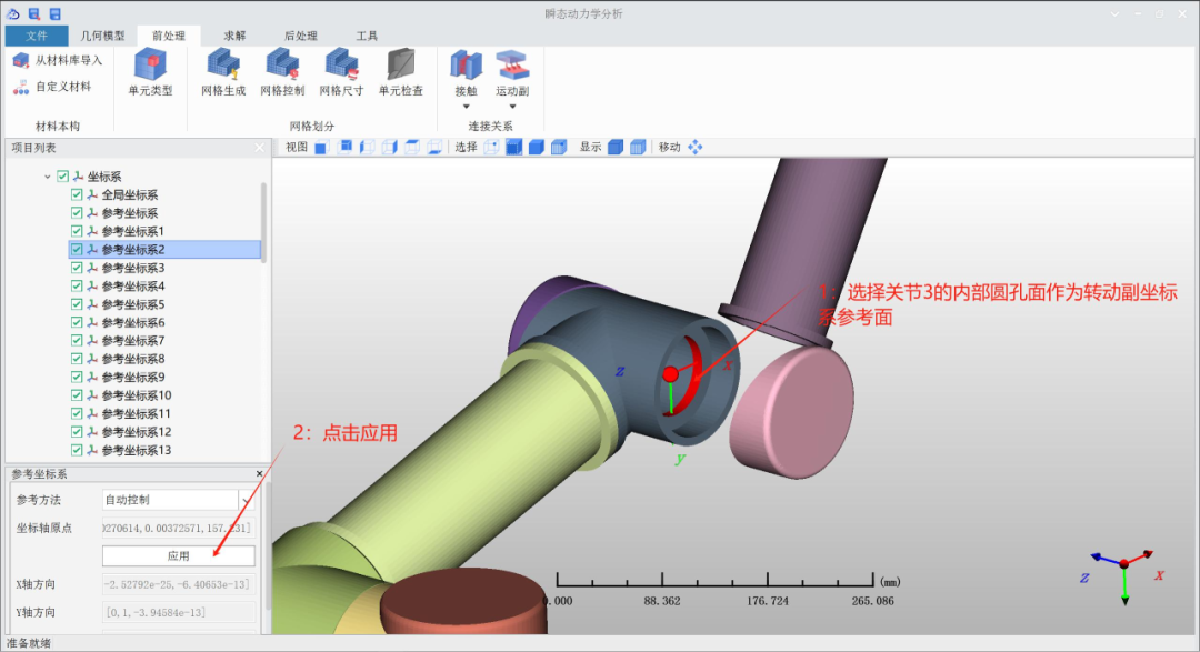
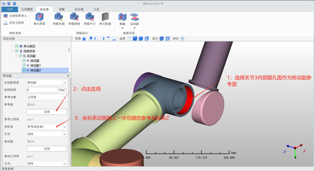
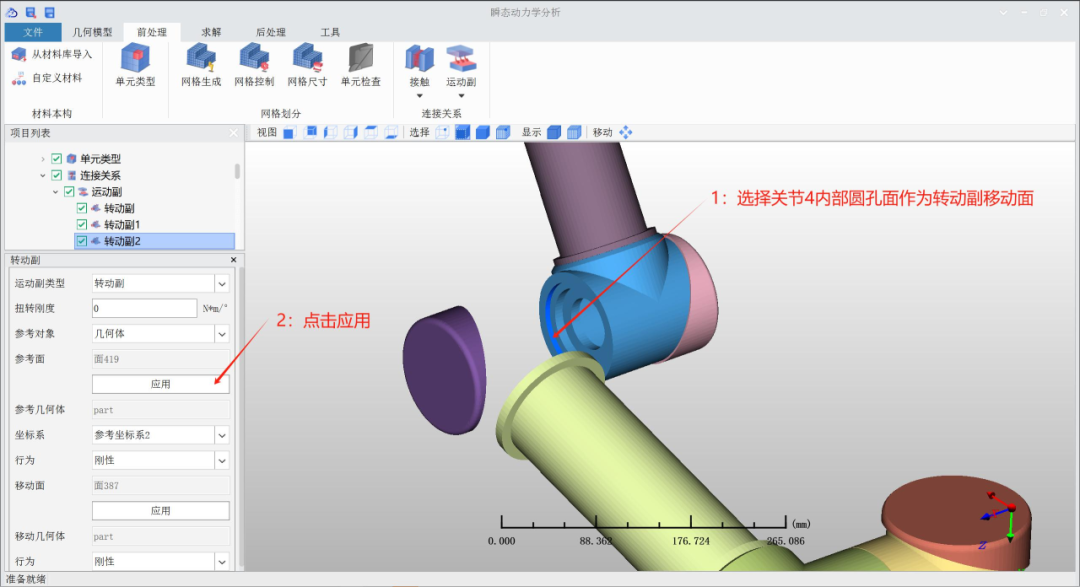
6.4 Establishing the rotational pair between Joint 5 and Joint 6
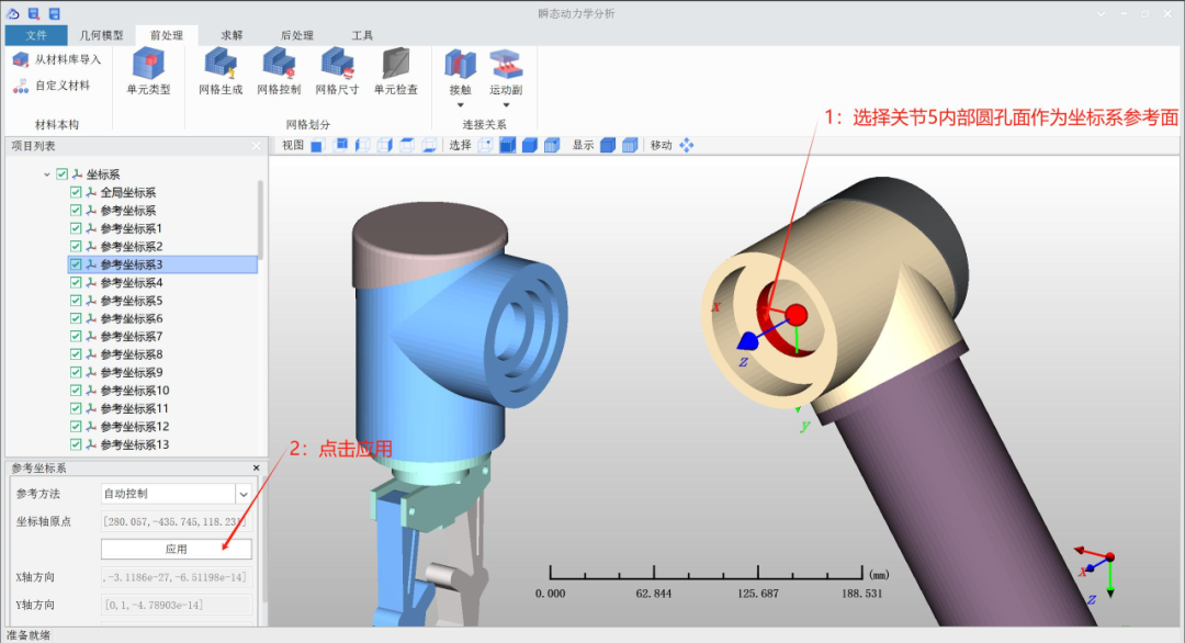
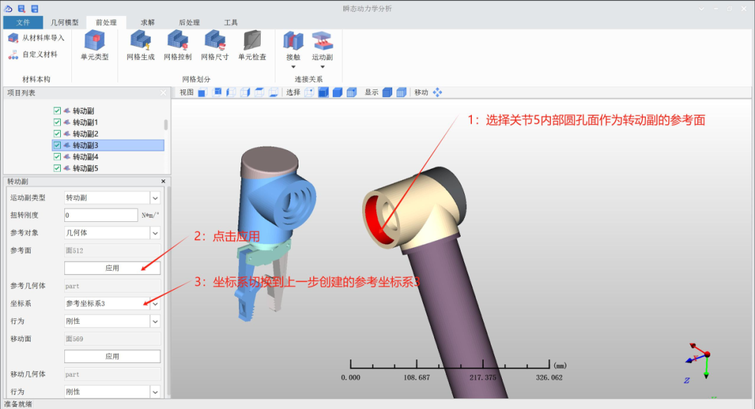
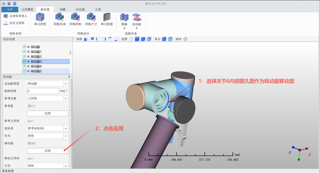
6.5 Establishing the rotational pair between Joint 6 and Joint 7
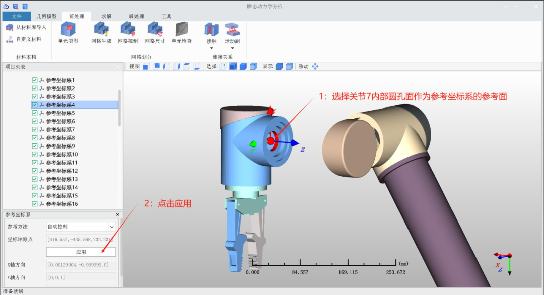
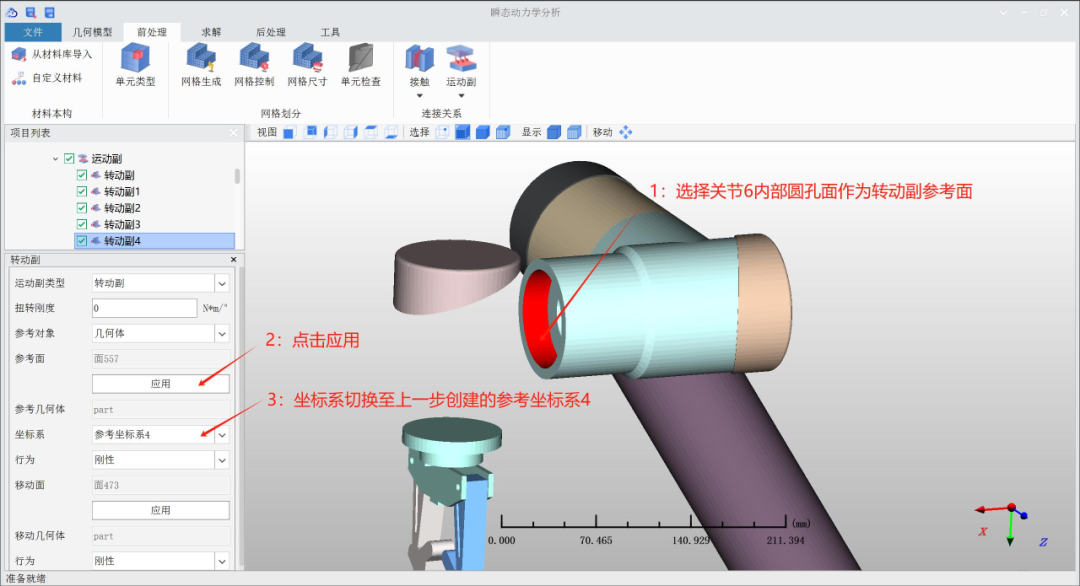
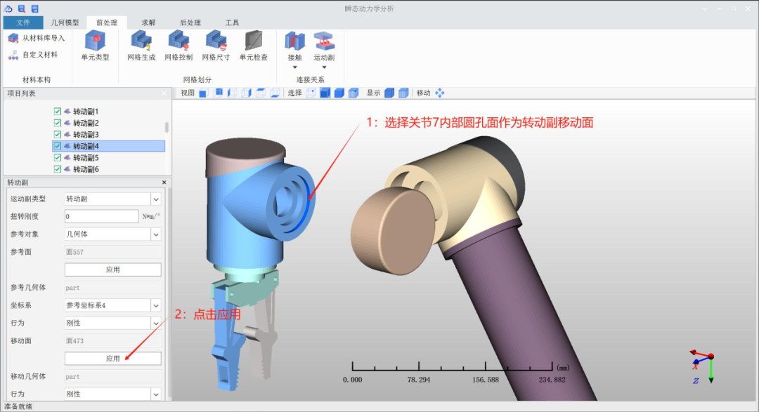
6.6 Establishing the rotational pair of the mechanical claw
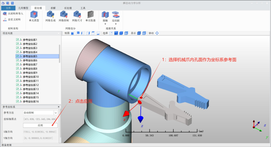
6.7 Establishing fixed pairs and their corresponding reference coordinate systems
Fixed pairs require their corresponding reference coordinate systems to ensure correct subsequent solutions. The corresponding reference coordinate systems can be established first, followed by the creation of fixed pairs.
6.7.1 Establishing the corresponding reference coordinate systems
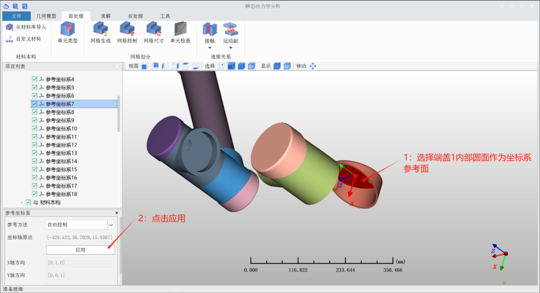
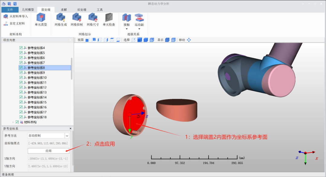
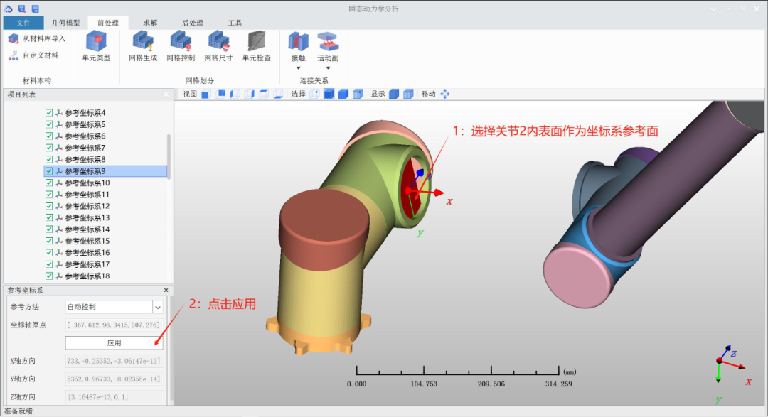
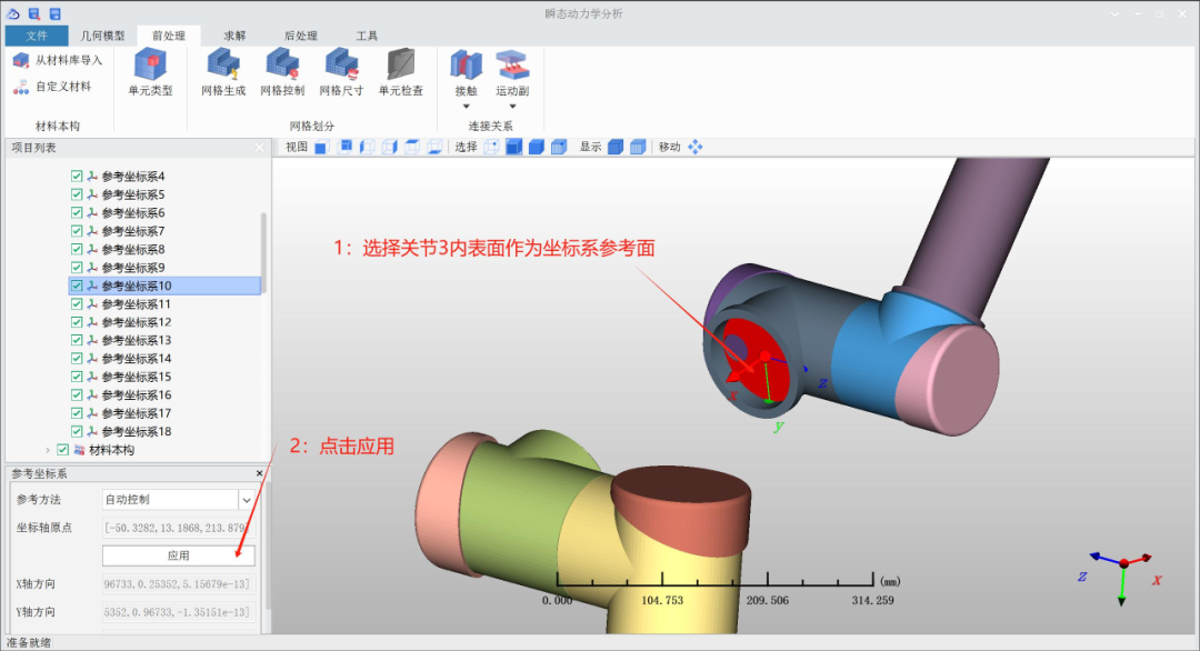
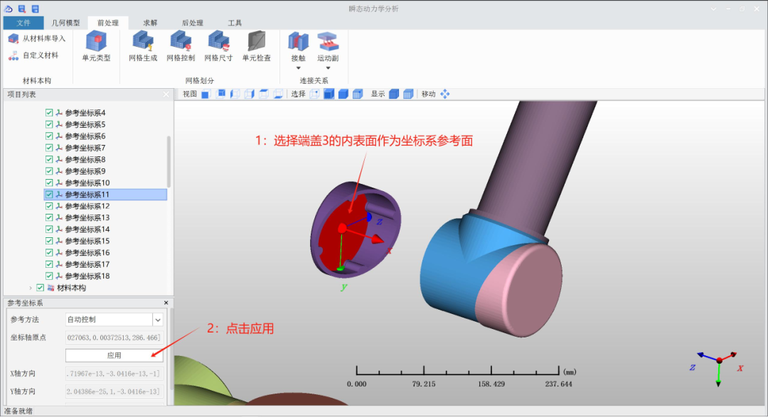
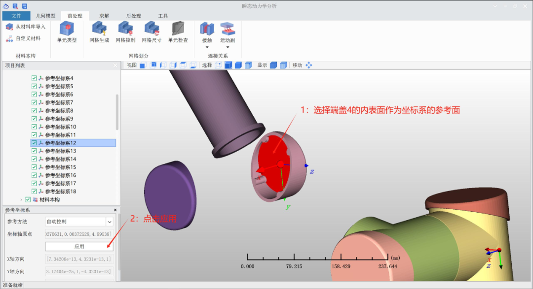
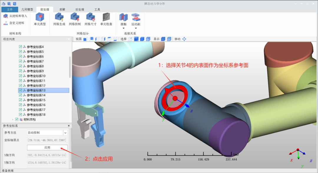
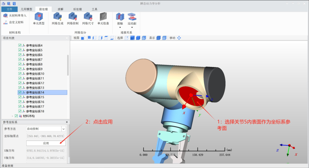
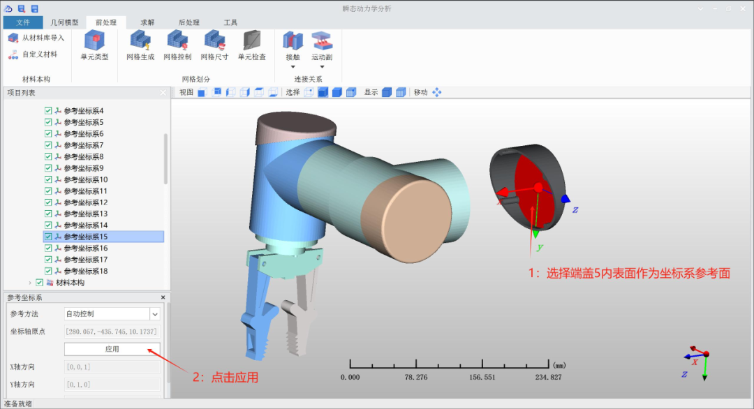
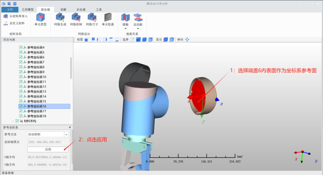
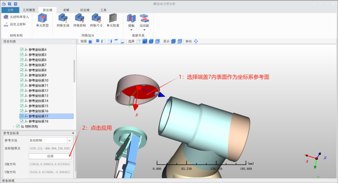
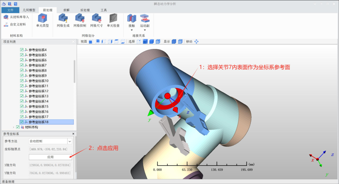
Thus, the creation of 12 sets of fixed pairs corresponding to reference coordinate systems is completed, and now we proceed to create the fixed pairs.
6.7.2 Creating fixed pairs between joints and end caps

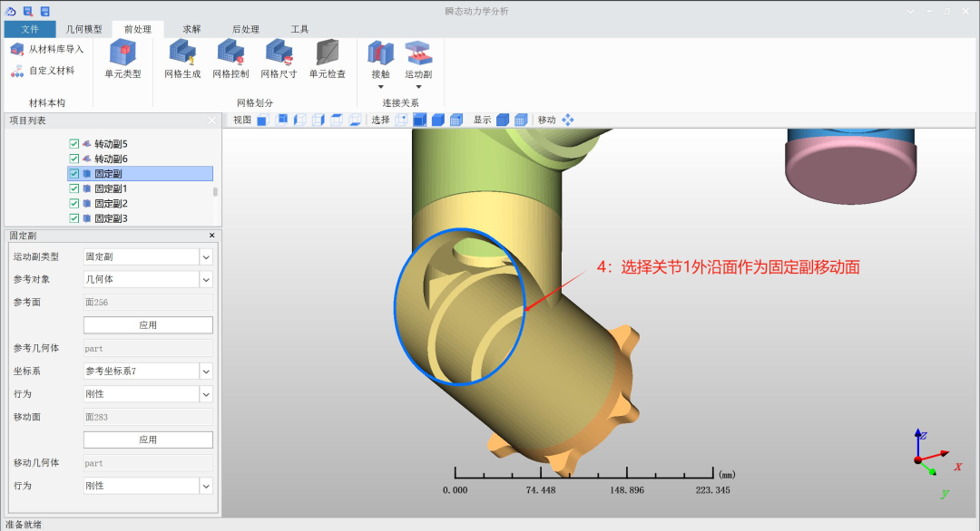
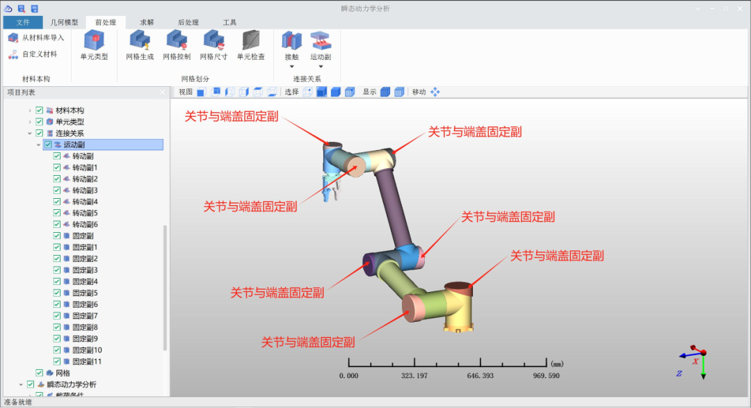
Excluding the fixed pair already established between Joint 1 and End Cap 1, the remaining 6 sets of fixed pairs can be established in the same manner, ensuring the matching of fixed pairs with their corresponding reference coordinate systems.
6.7.3 Creating fixed pairs between joints and connecting arms
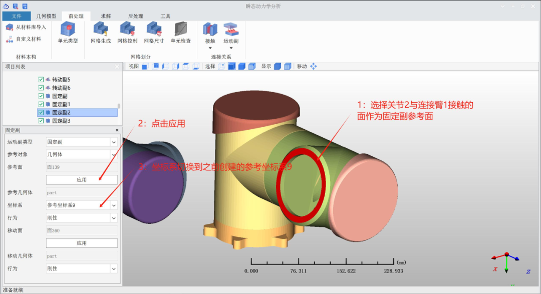
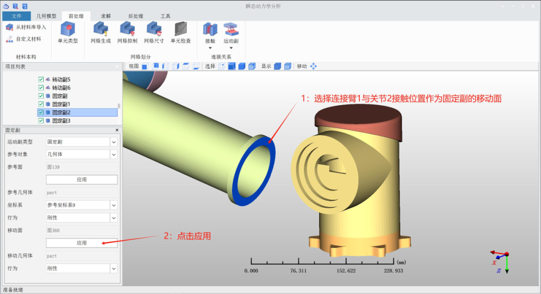
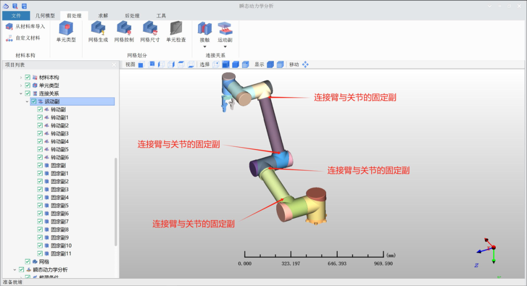
Excluding the fixed pair already established between Joint 2 and Connecting Arm 1, the remaining 3 sets of fixed pairs can be established in the same manner, ensuring the matching of fixed pairs with their corresponding reference coordinate systems.
6.7.4 Creating fixed pairs between joints and adapters
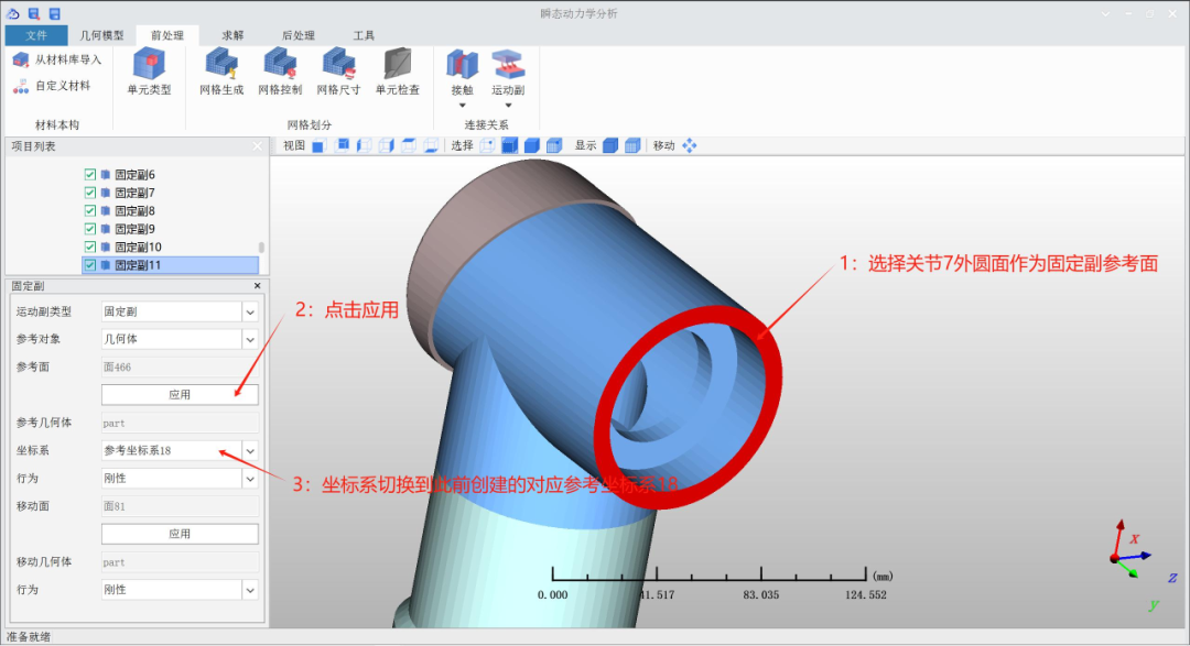
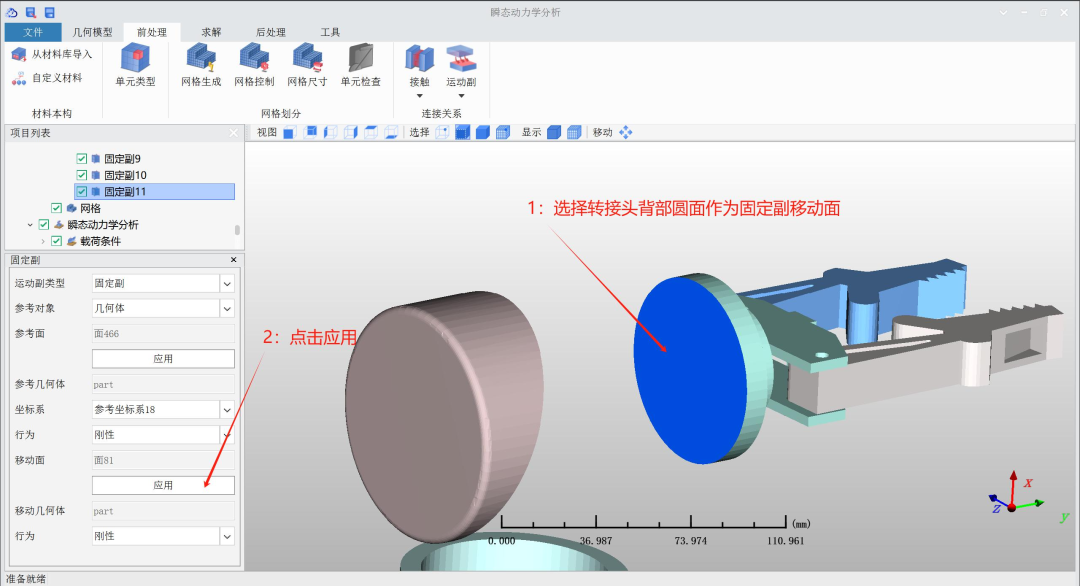
7

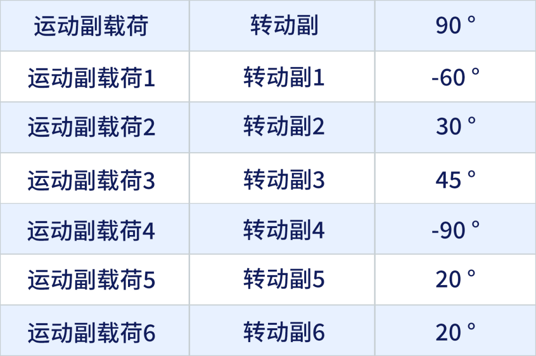
Applying the load
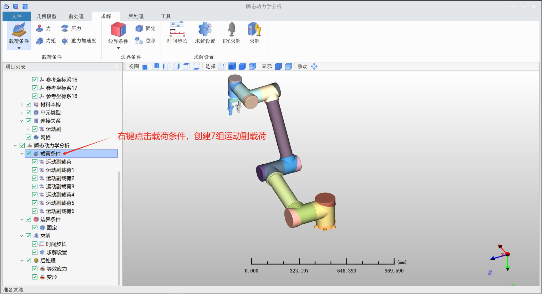
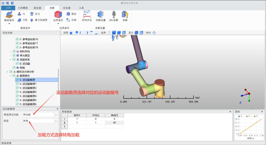
The load applied to the motion pairs and the corresponding angular data relationship is shown in the table below;
8

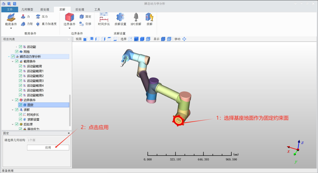
Determining boundary conditions
9

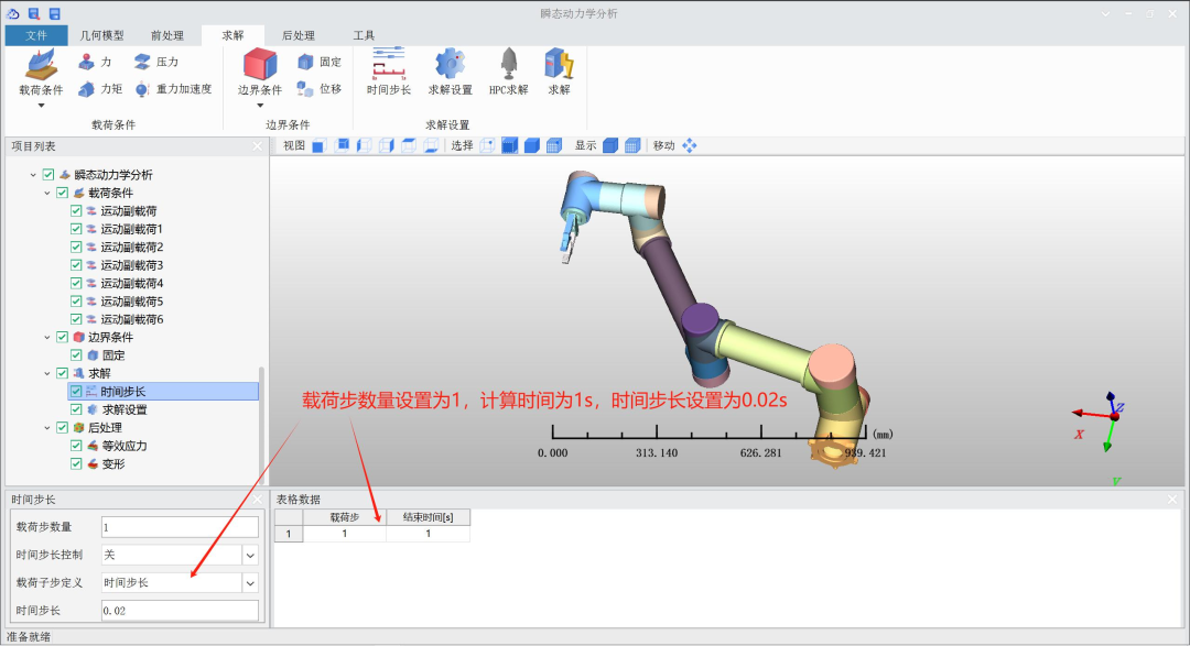
Determining load conditions
10

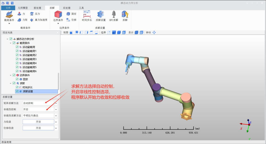
Setting up the solution
11

Solve
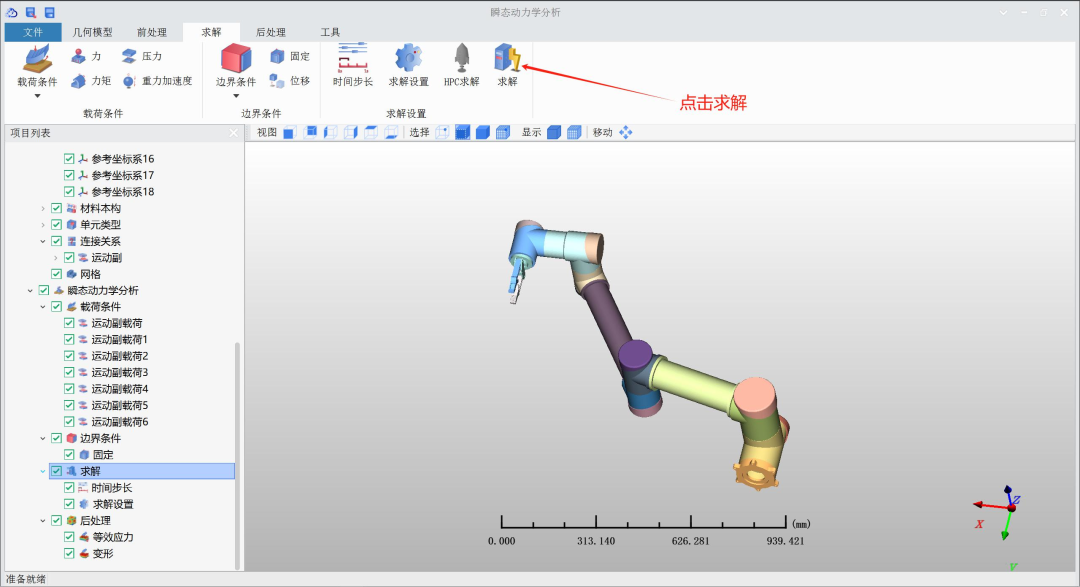
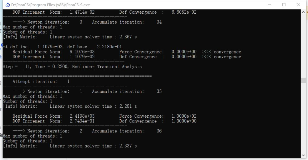
The program starts solving normally
12

Post-processing
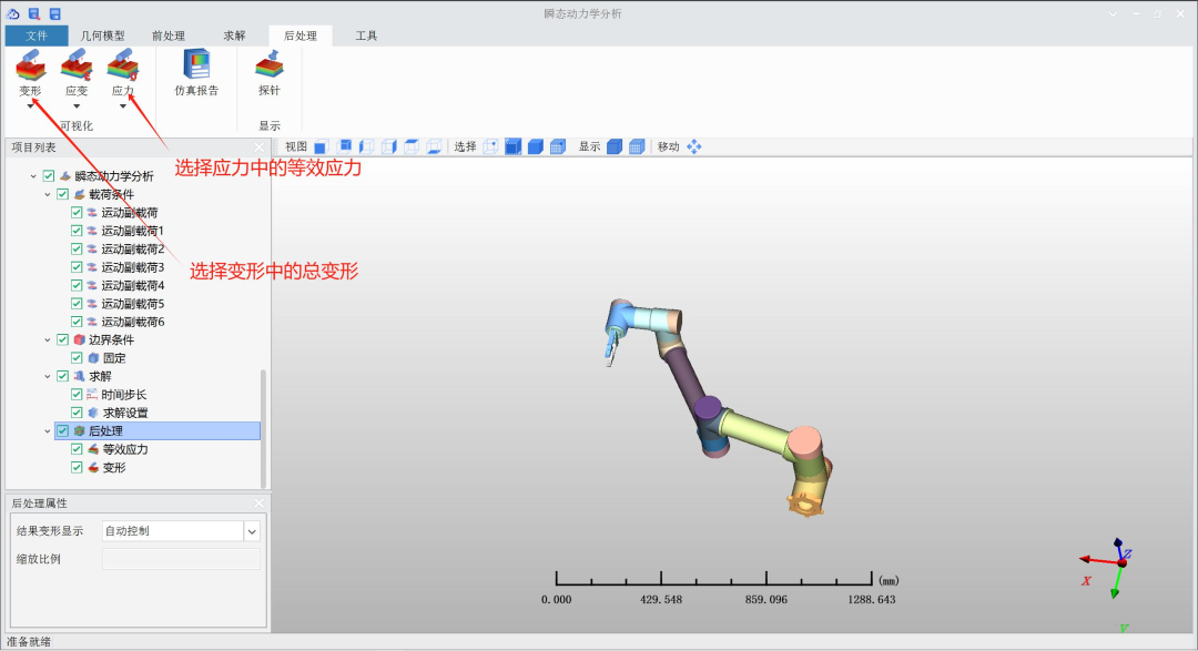
After the solution is completed, right-click to start post-processing to evaluate the results; the result deformation display can be selected as needed.

Structural equivalent stress cloud map
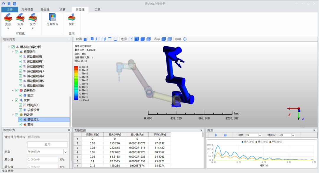

Structural total deformation cloud map