At the beginning of 2022, as the leaders of the new forces, various companies submitted their annual sales reports. The original “Weilai, Xiaopeng, and Li Auto” has transformed into “Xiaopeng and Li Auto,” with Xiaopeng achieving sales of 98,155 units, making it the sales champion among new forces. The biggest contributor to this is the P7, which contributed 60,569 units, accounting for 62%, making it a solid pillar.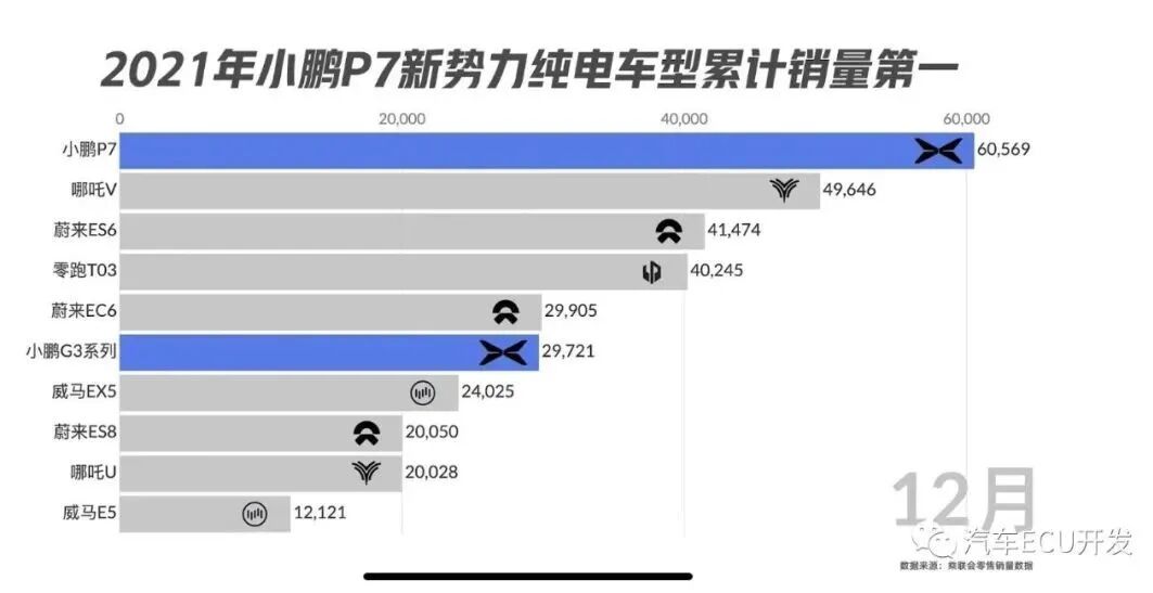 Xiaopeng is perceived as a technology-driven company, and the technical strength of the P7 is evident from media evaluations and impressive sales.For technology enthusiasts, the P7’s solid technical capabilities further spark curiosity about the internal technical implementations of the P7.01.Bus AnalysisADCAN:Personally understood as the Autonomous Driving CAN (ADAS CAN), mainly used for communication between the autonomous driving unit and the inertial measurement unit, vision module, radar, vehicle controller, and panoramic module.
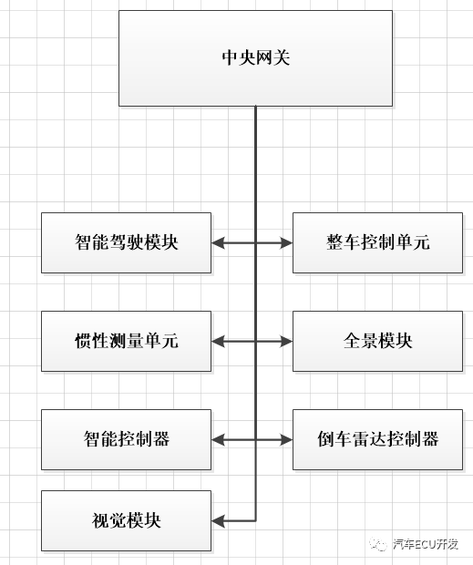 BCAN:BCAN should be the Body CAN, mainly used for CAN communication between body accessories, such as the body control module, seat belt control module, airbag control module, light control module, seat memory control module, and ambient light control module.
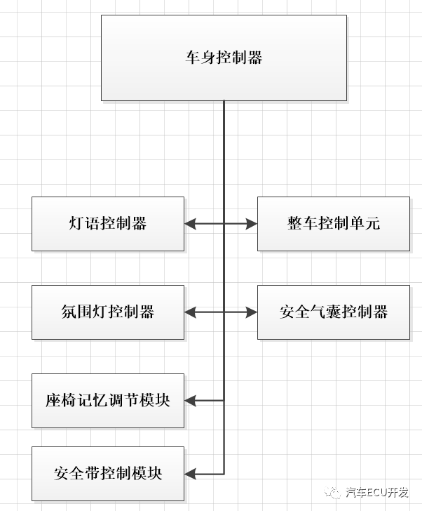
CCAN:
CCAN should be the Chassis CAN, used for connections between the electric power steering controller, electronic stability system, parking controller, intelligent modules, left and right rear millimeter-wave radars, vehicle controller, and autonomous driving unit.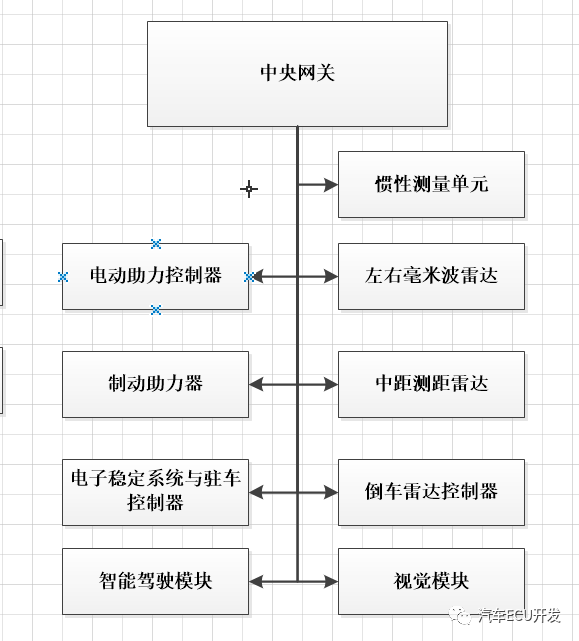 ECAN:ECAN is the New Energy CAN, mainly used for communication between the three electric systems of new energy, including the onboard power supply, motor controller, BMS, vehicle controller, and air conditioning controller.
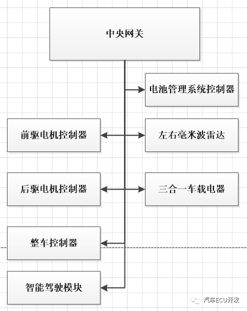
ICAN:
ICAN should be the Instrument CAN, used for communication between the instrument cluster, central control screen host, and central gateway.
 PRICAN:
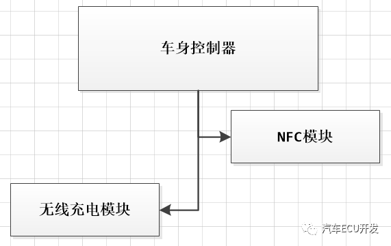
Used for communication between the vehicle controller and NFC module, wireless charging module.
 SCAN:Mainly used for communication between radar and autonomous driving unit, including right rear and right front millimeter-wave radars, left front and left rear millimeter-wave radars.
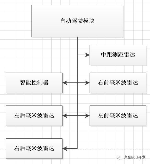
In addition to the CAN bus, LIN, Ethernet, and LVDS also exist, where LIN and LVDS are mainly used for connections with sensors, such as LVDS with cameras. The use of Ethernet can be seen from the OBD and central gateway connector interfaces.
| Pin | Meaning |
| IP33-16 | Power positive |
| IP33-6 | DCAN-H connected to the central gateway |
| IP33-14 | DCAN-L connected to the central gateway |
| IP33-12 | ETH-T+ connected to the central gateway |
| IP33-13 | ETH-T- connected to the central gateway |
| IP33-3 | ETH-R+ connected to the central gateway |
| IP33-11 | ETH-R- connected to the central gateway |
| IP33-8 | DOIP activation line |
| IP33-7 | CAN-H connected to the DC charging port and BMS |
| IP33-15 | CAN-L connected to the DC charging port and BMS |
| IP33-4, IP33-5 | GND |
Table 1 OBD Interface Definition02.P7 Autonomous Driving System AnalysisAs Xiaopeng’s flagship, autonomous driving cannot be overlooked. Its overall hardware configuration includes cameras, millimeter-wave radar, ultrasonic sensors, high-precision positioning, and the NVIDIA Xavier computing platform, with the overall architecture shown in the figure below.
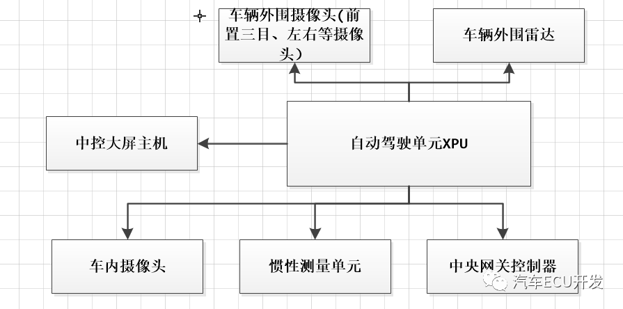
The interfaces of the XPU unit are shown in the table below:
| Pin | Meaning |
| BD19-6, BD19-1, BD19-2, BD19-3, BD19-4, BD19-5 | Power positive |
| BD19-20, BD19-21, BD19-22, BD19-23, BD19-24, BD19-25, BD19-33 | Ground |
| BD20-14, BD20-13 | LIN bus LIN-F, LIN_R connected to radar |
| BD19-15, BD19-14 | SCAN1-H, SCAN1-L |
| BD19-13, BD19-12 | SCAN2-H, SCAN2-L |
| BD19-19, BD19-18 | CCAN-H, CCAN-L |
| BD19-9, BD19-8 | ADCAN-H, ADCAN-L |
| BD136-1 | Connected to the left front camera |
| BD136-4 | Connected to the right front camera |
| BD136-2 | Connected to both cameras |
| BD131-1, BD131-2, BD131-4 | Connected to the front three-camera |
| BD138-1, BD19-37, BD19-39 | Connected to the in-car camera |
| BD131-3 | Connected to the rear side camera |
| BD136-3 | Connected to the right rear camera |
| BD146-4, BD146-3, BD146-2, BD146-1 | Connected to the central control screen host |
| BD147-1, BD147-2 | ETH+ and ETH- connected to the central gateway |
| BD147-5, BD147-6 | ETH+ and ETH- connected to the panoramic module |
| BD19-26 | PPS-GND |
| BD19-29 | IMU-PPS |
Table 2 XPU Interface Definition
03.High Voltage Power Down Process AnalysisThe high voltage power down process is mainly divided into normal power down and emergency power down:1. Normal Power DownDuring the high voltage process, in a high voltage state or charging state, KL15 power down, EBS without wake-up and no charging wake-up enters the power down process. During the power down process, high voltage devices are first stopped, and after all high voltage devices enter standby state, a high voltage power down command is sent to the BMS. After the high voltage contactor is cut off, high voltage components self-discharge, and when the input voltage of the high voltage components drops to a safe voltage, low voltage power supply is cut off. After the bus sleeps, the VCU enters sleep mode.2. Emergency Power DownDuring the high voltage process or in a high voltage state, if the system reports a power down fault, receives a collision signal, or if high voltage devices cannot enter standby during the power down process, it enters the emergency power down process. During the power down process, high voltage devices are first put into standby state, and if the time exceeds, a direct request for high voltage power down is made, cutting off the power supply of the high voltage contactor. After the high voltage contactor is cut off, if KL15 power down or collision signal is detected as valid, low voltage power supply is cut off. After the bus is closed, the VCU enters sleep mode.04.ConclusionThis is an overview of the internal technology of the Xiaopeng P7. From the network architecture perspective, the Xiaopeng P7 is relatively ordinary, with its main focus, as advertised, still on autonomous driving and intelligent cockpit. Last year, Xiaopeng unveiled the G9 at the Guangzhou Auto Show, which, in addition to the normal iteration of autonomous driving, also features the X-EEA 3.0 central supercomputing + regional control architecture, 800V fast charging, charging over 200km in 5 minutes, and full vehicle OTA, which is worth looking forward to.
Recommended Reading
Working Principle of LiDAR DetectionIntroduction to CAN Bus BasicsSummary of the Main Differences Between CANXL and CANFDIn-depth Analysis of the Differences Between CAN FD and Traditional CANDetailed Explanation of the Electronic and Electrical Architecture of LiDAR Porsche TaycanReflections on the Transformation of Automotive Professionals, “Positive Energy” Stories are Tiring, Today We Present a “Negative Energy” Collection of 2021 Articles, Everything You Want is Here!Academician Ouyang Minggao: The Skateboard Chassis Will Bring a Revolution to AutomobilesSome Thoughts on Traditional OEMsTesla AutoPilot Pure Vision Solution AnalysisHow to Write an Impressive Automotive Software RequirementUnderstanding Automotive ECU Software TestingAnalysis of Tesla’s Latest Central Computing Module (CCM)Detailed Overview of the ECU Interface of the 2021 Tesla Model YUnderstanding CAPL Programming in CANoeUnderstanding CAN Time SynchronizationDetailed Explanation of the dbc File Format and CreationIn-depth Explanation of the Bootloader Based on UDSUnderstanding the Power Down Process of the Whole VehicleDetailed Explanation of CAN Bus Error Frames | Download IncludedIntroduction to DoIP Protocol, Material Sharing!Detailed Development of the Vehicle Network OTA System | Download IncludedUnderstanding Automotive Embedded AUTOSAR Architecture | Download IncludedSafety Research on Tesla Autopilot System | Download Included dbcSharing is not easy, please give a thumbs up【Looking】