1. Core Fault Characteristic Analysis
-
Fault Phenomenon: ECU not functioning → Restored by reconnecting the harness → No physical damage to the connector
-
Essential Cause: Connection stability issue (not a permanent disconnection, but abnormal contact resistance or momentary signal interruption)
2. Five Fundamental Causes and Troubleshooting Methods
1. Poor contact of terminal micro-switches (approx. 40%)
-
Detection Method:
-
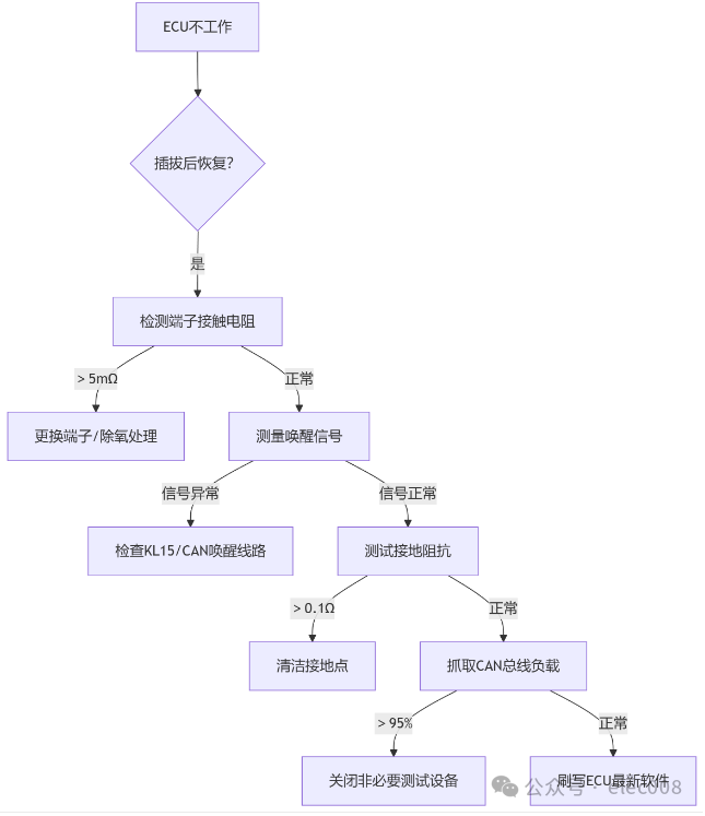
Contact resistance testing: Measure the resistance after terminal insertion with a milliohm meter (normal ≤ 5mΩ)
-
Micro-vibration testing: Monitor ECU power supply voltage while lightly tapping the connector (fluctuation > 0.2V is abnormal)
-
Typical Scenarios:
-
Insufficient pre-tension of terminal spring ( < 1N)
-
Oxidation of the coating surface (caused by storage humidity > 60%)
2. ECU Wake-up Logic Conflict
-
Abnormal wake-up signal:
Wake-up Type Detection Point Normal Signal Hard-wired wake-up KL15 line voltage (ignition switch) Instantaneous ≥ 10.5V CAN wake-up CAN-H/L differential voltage (during sleep) 0V → 2.5V transition -
Diagnostic Tool: Oscilloscope captures wake-up signal timing (if the interval between KL15 and CAN wake-up > 500ms, it will cause ECU reset)
3. Harness Assembly Stress Release
-
Fault Mechanism: Excessively sharp installation angle of the harness (bending radius < 6D, where D is the wire diameter) → Partial internal wire fracture → Temporary reset during insertion/removal
-
Verification Method:
-
X-ray inspection: Check the condition of the wires at the connector’s rear
-
Tensile testing: Apply a force of 50N to a single wire (displacement > 2mm indicates failure)
4. Abnormal Ground Loop Impedance
-
Key Detection Points:
Ground Point Allowed Impedance Failure Consequence ECU chassis ground < 0.1Ω ECU cannot start Sensor reference ground < 0.5Ω Signal drift leads to logical errors -
Case: A certain model’s ECU grounding bolt was coated with sealant (insulation resistance > 100MΩ)
5. Software Initialization Timeout
-
Diagnostic Codes Pointing To:
-
U0140 (communication loss with ECU)
-
P0606 (ECU processor fault)
-
Trigger Conditions:
-
CAN bus load rate > 95% (e.g., production line testing equipment broadcasting interference)
-
ECU power-on self-test > 3s (calibration requirement ≤ 2s)
3. Quick Troubleshooting Process on the Production Line
4. Root Cause Mitigation Measures (Production Optimization)
1. Connector Process Upgrade
| Improvement Item | Original Process | Optimized Plan |
|---|---|---|
| Terminal crimping force | 50±10N | 80±5N (to enhance contact stability) |
| Coating process | Tinning (0.5μm) | Gold plating (0.8μm) + anti-oxidation coating |
| Insertion and extraction life testing | 50 cycles | 100 cycles + micro-vibration monitoring |
2. Wake-up Logic Error Prevention Design
-
Hardware Improvement: Add wake-up signal filtering capacitor (10μF) → Avoid voltage spikes
-
Software Fault Tolerance:
-
// Example: Dual wake-up signal interlock logicif(KL15_Status || CAN_Wakeup){ ECU_Enable =1;// Any wake-up valid triggers start}else{ ECU_Enable =0;}
3. Harness Assembly Specifications
-
Bending Radius: Enforced ≥ 8 times the wire diameter (e.g., wire Φ2mm → bending radius ≥ 16mm)
-
Stress Relief: Add tie-down points within 150mm of the connector’s rear
4. Electrostatic Protection (ESD)
-
High-Risk Workstations: ECU installation area, harness insertion and extraction stations
-
Control Measures:
-
Ion wind machines neutralize charges (static voltage < 100V)
-
Operators wear wrist straps (ground resistance 1MΩ)
5. Typical Fault Cases
Case 1: Micro-corrosion of terminals leading to intermittent ECU failure
-
Phenomenon: 8% ECU failure rate for new cars off the production line, restored after reconnection
-
Analysis:
-
Terminal contact resistance reached 120mΩ (standard 5mΩ)
-
Storage environment humidity of 70% accelerated oxidation of the tin layer
-
Solution:
-
Add dehumidifiers in the warehouse (humidity controlled at 40±5%)
-
Add vapor corrosion inhibitor (VCI) packaging for terminals
Case 2: CAN wake-up conflict causing ECU crash
-
Phenomenon: ECU unable to wake up at the end of the assembly line
-
Root Cause:
-
Diagnostic equipment continuously sending wake-up frames → CAN bus load rate 98%
-
ECU unable to process its own wake-up request
-
Optimization:
-
Modify diagnostic protocol: turn off broadcast messages after entering production line mode
-
Add hardware watchdog (reset ECU after 500ms timeout)
6. Long-term Prevention Mechanism
-
Data Monitoring
-
Establish ECU failure parts database (record VIN, workstation, fault codes)
-
Use AI clustering to analyze high-frequency failure modes (e.g., specific terminals/ground points)
Testing Reinforcement
-
Add ECU “Insertion-Extraction-Vibration” Combined Testing (simulating vehicle vibrations)
-
100% execution of automated ground impedance testing (add milliohm meter at EOL workstation)
Summary: The core of such faults is the “contact resistance + signal timing + environmental stress” superposition effect. The production side needs to focus on:
-
Terminal Reliability: Increase gold plating thickness to 0.8μm + crimping force 80N
-
Wake-up Robustness: Dual wake-up redundancy + CAN load rate control
-
Stress Control: Minimum bending radius of harness 8D + electrostatic protection Through precise measurement of contact resistance and strict timing analysis, the root cause can be quickly identified, reducing the offline failure rate to below 0.1%.